Hearing aid system comprising a matched filter and a measurement method

a filter and hearing aid technology, applied in the field of hearing aid systems, can solve problems such as inability to implement, and achieve the effect of improving the signal-to-noise ratio of hearing aids

Active Publication Date: 2009-06-11
OTICON
View PDF38 Cites 18 Cited by
  • Summary
  • Abstract
  • Description
  • Claims
  • Application Information

AI Technical Summary

Benefits of technology

[0019]An advantage of the invention is that it provides an alternative scheme for improving signal to noise ratio of a hearing aid.
[0020]In an embodiment, the hearing aid system comprises a signal path comprising a signal processing unit for processing the digital input signal—at least for adapting the digital input signal to a user's hearing profile—and for providing a processed output signal. The signal path (also termed the forward path) comprises the signal picked up by the input transducer to be processed by the signal processing unit and the components for processing the signal to be presented (e.g. via an output transducer) as an audio signal adapted to a user's needs.
[0021]In an embodiment, the hearing aid system comprises a D / A converter for converting a processed output signal to an analogue electrical output signal. A predefined sampling rate, e.g. between 5 and 20 kHz, can be used to create frames of digitized signal values of amplitude versus time comprising values at specific points in time, corresponding to n·(1 / fs) where fs is the sampling frequency and n=1, 2, 3, . . . . In an embodiment, the electrical input signal is split into a number of frequency bands (e.g. 4 or 8 or 16 or more) that are treated individually. In an embodiment, the frequency range considered is between 0 and 20 kHz, such as between 10 Hz and 10 kHz. In an embodiment, frames of digitized values of amplitude versus time are generated for each frequency band (and for a number of discrete frequencies in each band), thereby generating a digital time-frequency matrix.
[0022]In an embodiment, the hearing aid system comprises an output transducer, such as a receiver, for converting a digital or analogue electrical output signal to an output sound signal.
[0023]In an embodiment, the hearing aid system comprises a signal generator for generating a predefined source signal s(t). In an embodiment, the predefined source signal s(t) is periodic in time, e.g. comprising a sine and / or cosine signal (e.g. s(t)=sin(ω0·t), ω0=2π·f, where f is the frequency).
[0024]In an embodiment, the hearing aid system is adapted to provide that the source signal can be added to the output of the signal processing unit, e.g. via a digital SUM-unit, possibly controlled by a switch for enabling or disabling the source signal from the signal generator to the SUM-unit.

Problems solved by technology

An ideal matched filter is a non-causal system and cannot be implemented.

Method used


Image

  • Hearing aid system comprising a matched filter and a measurement method
  • Hearing aid system comprising a matched filter and a measurement method
  • Hearing aid system comprising a matched filter and a measurement method

Examples


example

“Critical Gain Measurement”

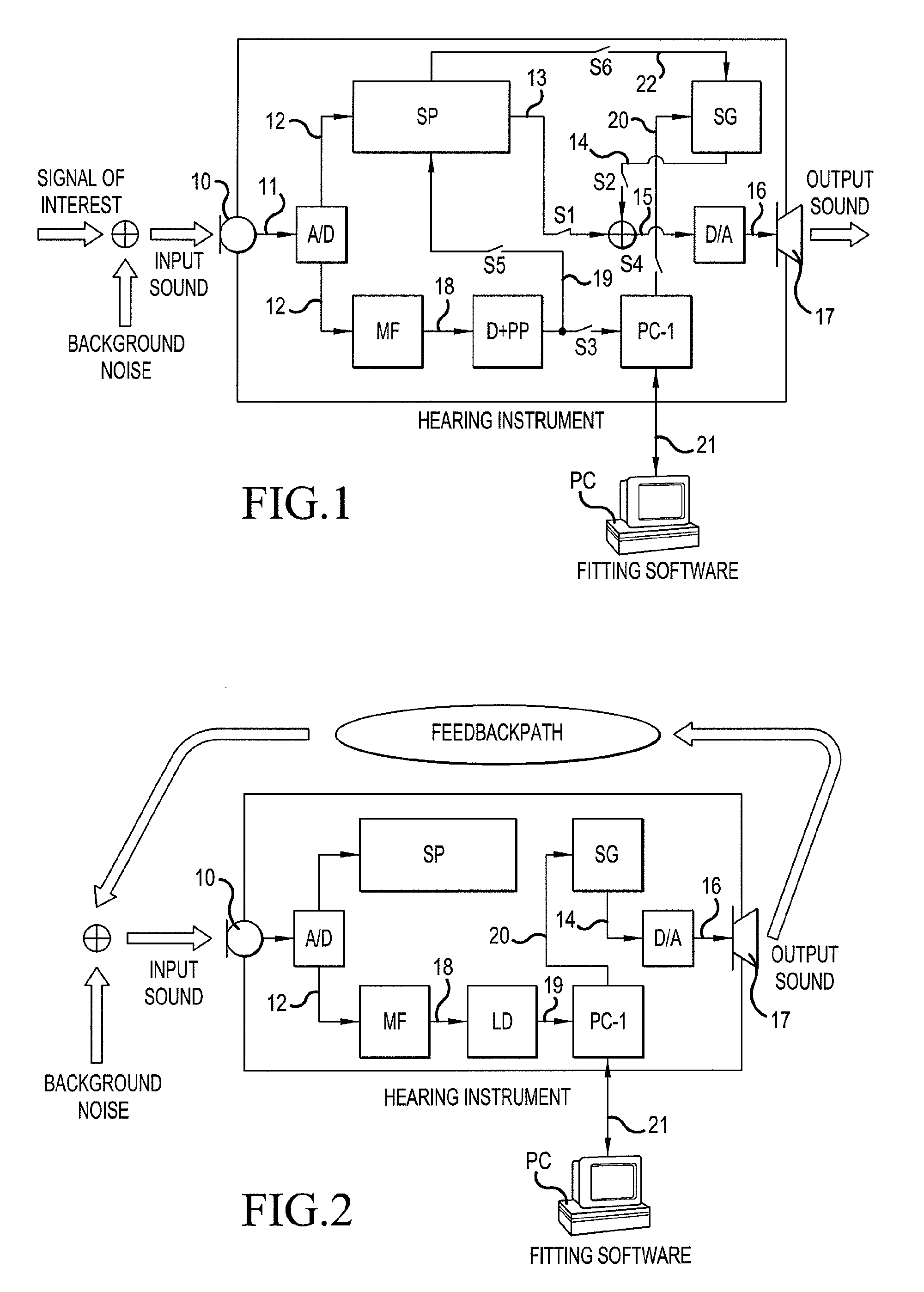
[0081]FIG. 2 is an illustration of a critical gain measurement using a hearing aid system according to an embodiment of the invention. The components of the hearing instruments shown in FIG. 2 are identical to those shown in FIG. 1, but their interconnection is different. The Detector+Post-processing unit of FIG. 1 is substituted by a Level detector (LD) in FIG. 2. The purpose of the Level detector is to measure level of signal produced by the signal generator that is picked up by the Hearing Instrument's input transducer. Subtracting the level of the signal that was produced by the signal generator from the measurement result on the dB scale yields an estimate of the transfer function between signal generator and Level detector at the frequency or frequency range of the signal emitted by the signal generator. The Level detector can be implemented as follows: its input signal is rectified or squared and then passed to a short-time integrator that applies o...

examples

“Automatic / Normal Mode”

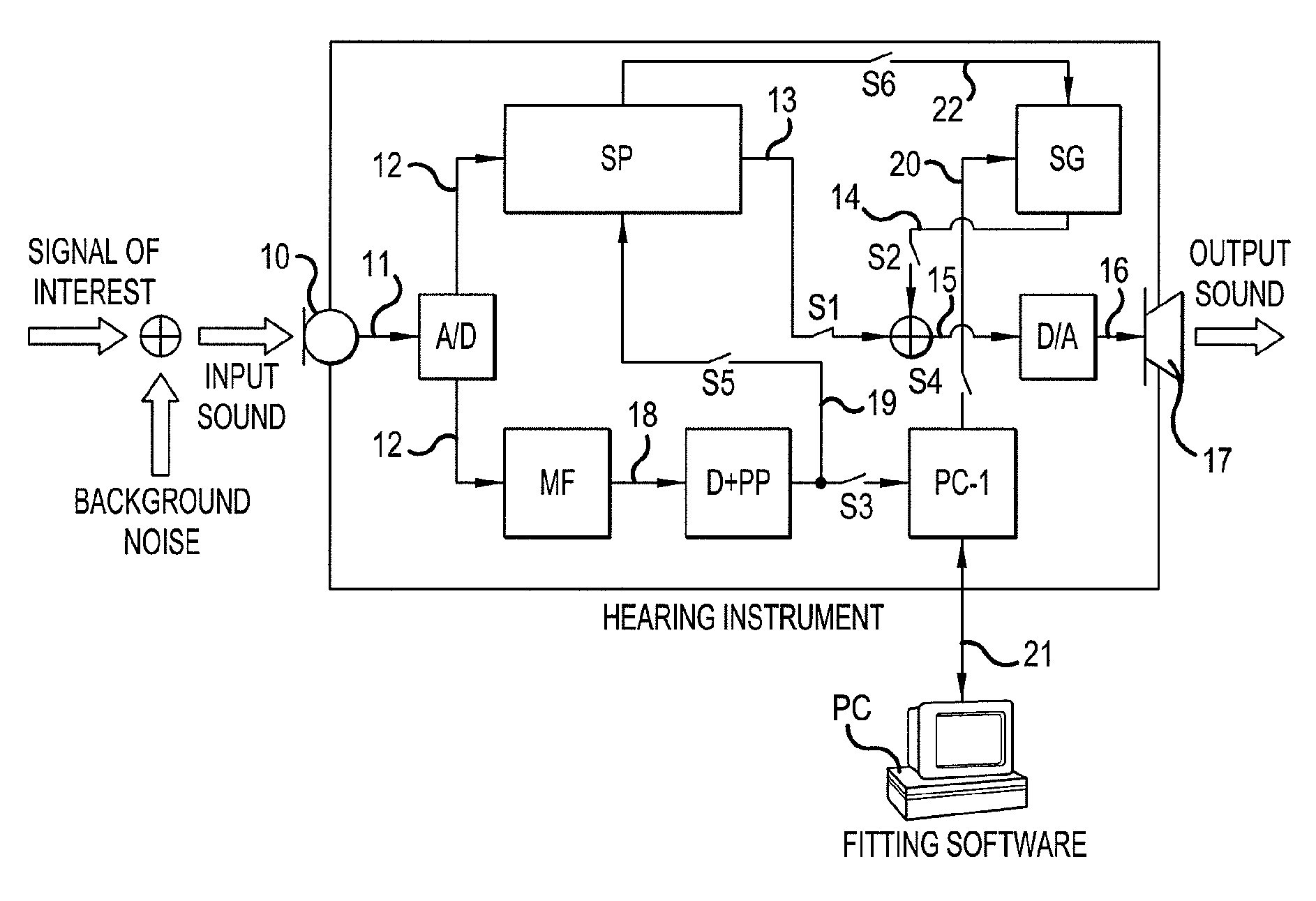
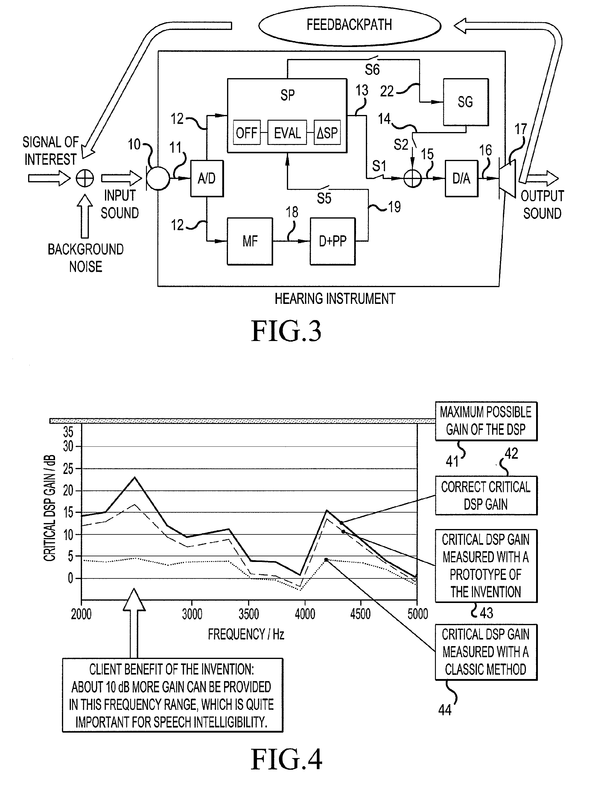
[0104]FIG. 3 shows an illustration of a configuration of a hearing aid system according to an embodiment of the invention in a normal operating mode. As illustrated in FIG. 3, a signal generator (SG) in the Hearing Instrument generates a predefined source signal 14, which is transformed to an output sound by the Hearing Instrument's output transducer 17. By measuring the level of that signal at the input transducer 10 of the Hearing Instrument, certain properties of the acoustic path (Feedbackpath) can be determined (e.g. transfer function and average gain). The measurement accuracy can be improved if the input signal is passed through a matched filter (MF) before the level measurement (in the detector unit D+PP), as is the case in the embodiment of FIG. 3. The measured properties of the acoustic path can be used to analyze the Hearing Instrument wearers current acoustic environment and to react to it appropriately. This is illustrated in FIG. 3 in that the ou...


PUM


Abstract

The invention relates to a hearing aid system comprising an input transducer for converting an input sound signal comprising an information signal part of a known waveform and a background noise part to an electrical analogue input signal, optionally an A/D converter for converting the electrical input signal to a digital input signal. The invention further relates to a method of making a critical gain measurement. The object of the present invention is to improve the signal-to-noise ratio of a signal to be measured or detected in a hearing instrument compared to prior art solutions. The problem is solved in that a matched filter receiving said analogue or digital input signal and optimized to improve the identification of the information signal part from the noisy input signal. An advantage of the invention is that it provides an alternative scheme for improving signal to noise ratio of a hearing aid. The invention may e.g. be used for the customization of hearing aid parameters in cooperation with fitting software and/or for improving signal to noise ratio of a detected or measured signal.

Description

TECHNICAL FIELD[0001]The invention relates to a scheme for improving signal to noise ratio in a hearing aid (HA, also interchangeably termed ‘Hearing Instrument’ (HI) in the following). The invention further relates to a method of making a critical gain measurement. The invention relates specifically to a hearing aid system, to a method and use.[0002]The invention may e.g. be useful for the customization of hearing aid parameters in cooperation with fitting software and / or for improving signal to noise ratio of a detected or measured signal.BACKGROUND ART[0003]Signal detection and measurements play an important role in the application of Hearing Instruments. Among other things, they allow us to collect information about the different acoustic environments in which a Hearing Instrument is worn, to assess Hearing Instrument performance, to collect the data needed for user-specific Hearing Instrument adjustments and to verify that the Hearing Instrument operates properly after a repair...

Claims


Application Information

Patent Timeline
Patent Type & Authority Applications(United States)
IPC IPC(8): H04R25/00
CPCH04R25/453H04R25/505H04R2225/41H04R25/558H04R25/70
Inventor LAMM, JESKOMAURER, LUKASERNST, MICHAELBOSTOCK, SARAH
Owner OTICON
Why Eureka
Try Eureka