Illumination systems, devices, and methods for biomass production

a biomass and illumination system technology, applied in the field of illumination systems, can solve the problems of inability to meet the needs of biomass production, etc., to achieve the effect of reducing biomass production cost, increasing biomass production, and cost-effective operation

Inactive Publication Date: 2009-06-11
BIONAVITAS
View PDF64 Cites 214 Cited by
  • Summary
  • Abstract
  • Description
  • Claims
  • Application Information

AI Technical Summary

Benefits of technology

[0033]In some embodiments, an illumination system for biomass production includes a plurality of light-diffusing members, a passive light energy system, and an activatable auxiliary system. The passive light energy system is optically coupled to the plurality of light-diffusing members and receives solar light energy and delivers the solar light energy to the members. The activatable auxiliary system is also optically coupled to the plurality of light-diffusing members. The activatable auxiliary system is adapted to receive electrical energy and to generate non-solar light energy that is delivered to the plurality of elongate light-diffusing members. In some embodiments, the passive light energy system delivers solar light energy to a first group of the light-diffusing members and the activatable auxiliary system delivers light energy to a separate group of the light-diffusing members. In some embodiments, the passive light energy system and the activatable auxiliary system concurrently deliver light energy to the same light-diffusing members. When an insufficient amount of solar light energy is available (e.g., at night), the activatable auxiliary system can be used to produce a sufficient amount of non-solar light energy for biomass production. Thus, biomass production can be maintained throughout an entire day even when available solar light falls below a threshold level, for example, during the period of the day between dusk and dawn.
[0037]The solar collector end, in some embodiments, extends outwardly with respect to a longitudinal axis of the member. The solar collector end, for example, may extend outwardly beyond at least a portion of or the entire outer surface of the main body. The solar collector end may have a generally v-shaped profile, u-shaped profile, spherical configuration, or flat configuration, as well as any other shape suitable for providing an enlarged feature for receiving solar energy. As such, the solar collector end can collect more solar light energy as compared to an end of a member having a substantially uniform profile along its longitudinal length.

Problems solved by technology

The fluorescent or incandescent lamps typically used, however, are not generally energy efficient or durable (long lasting).
If the light intensity is too high or the exposure time too long, the growth of the algae is inhibited.
These open-air systems are further limited by an inability to substantially control the various process parameters (e.g., temperature, incident light intensity, flow, pressure, nutrients, and the like) involved in cultivating algae.
Alternatively, biomasses are cultivated in closed systems called “bioreactors.” These closed systems allow for better control of the process parameters, but are often more costly to set up and operate.
In addition, these closed systems are limited in their ability to provide sufficient light to sustain dense populations of photosynthetic organisms cultivated within.

Method used


Image

  • Illumination systems, devices, and methods for biomass production
  • Illumination systems, devices, and methods for biomass production
  • Illumination systems, devices, and methods for biomass production

Examples


Embodiment Construction

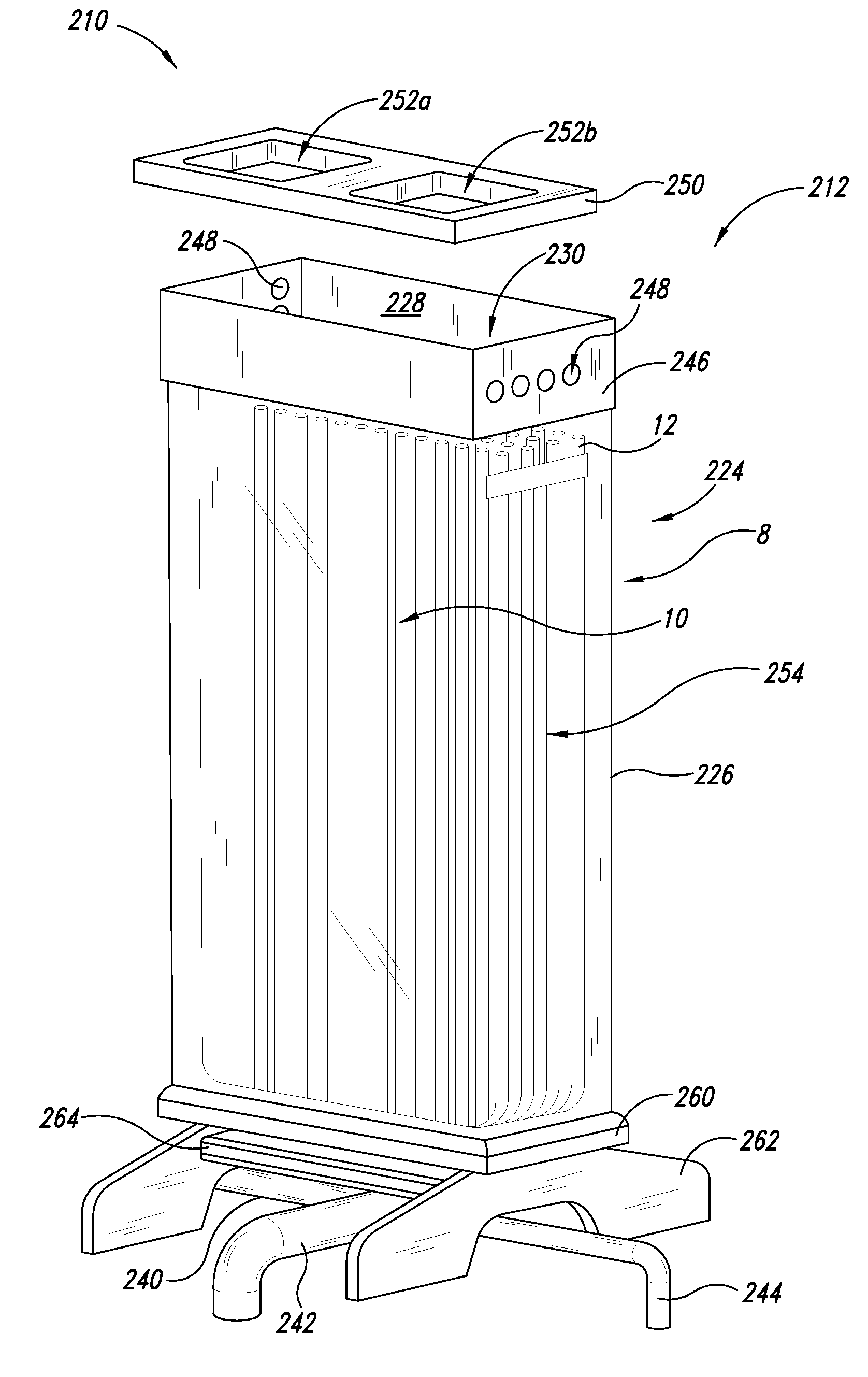
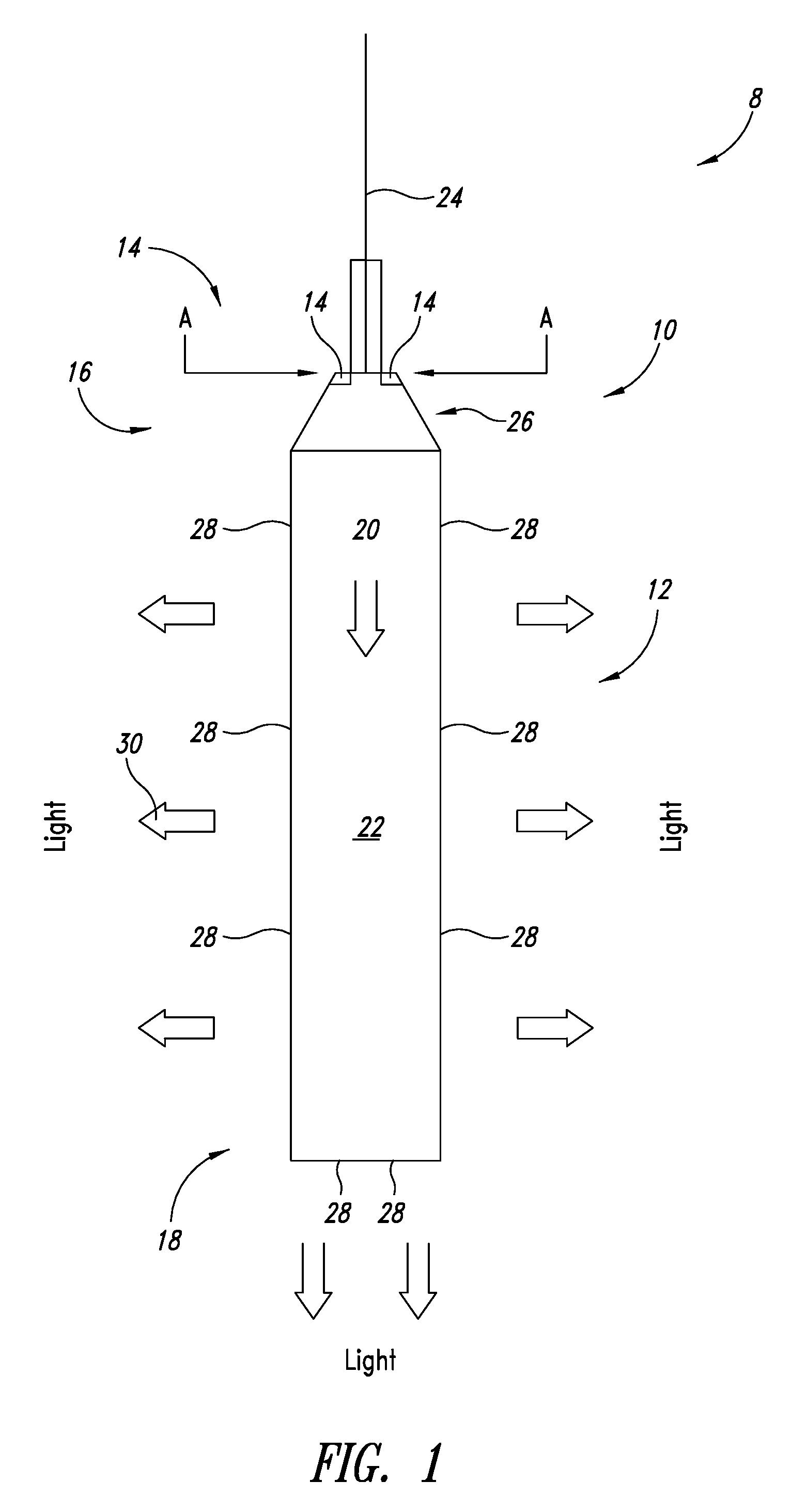
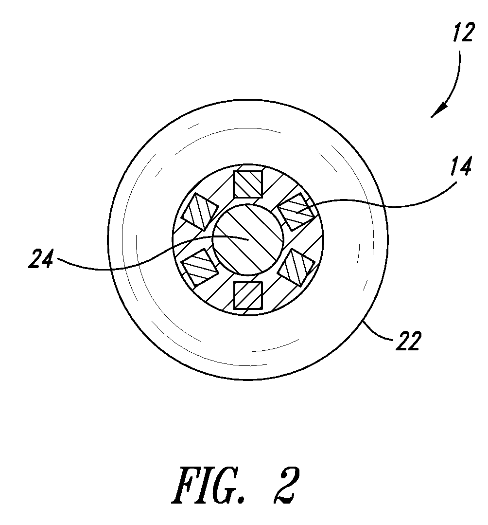
[0061]In the following description, certain specific details are included to provide a thorough understanding of various disclosed embodiments. One skilled in the relevant art, however, will recognize that embodiments may be practiced without one or more of these specific details, or with other methods, components, materials, etc. In other instances, well-known structures associated with bioreactors, the transmission of effluent streams into and out of a bioreactor, the photosynthesis and lipid extraction processes of various types of biomass (e.g., algae and the like), fiber optic networks to include optical switching devices, light filters, solar collector systems to include solar array cells and solar collector mechanisms, methods of monitoring and harvesting a biomass (e.g., algae, and the like) to extract oil for biofuel purposes and / or convert a treated biomass (e.g., algae, and the like) to feedstock may not have been shown or described in detail to avoid unnecessarily obscur...


PUM

PropertyMeasurementUnit
peak emission wavelengthaaaaaaaaaa
concentrationaaaaaaaaaa
first peak emission wavelengthaaaaaaaaaa

Abstract

Illumination systems, devices, and methods for cultivating biomasses. A bioreactor system is operable for growing photosynthetic organisms. The bioreactor system includes a bioreactor and an illumination system. The illumination system includes one more optical waveguides configured to light at least some of a plurality of photosynthetic organisms retained in the bioreactor. In some embodiments, the one or more optical waveguides include a plurality of structures configured to direct light energy from a solar energy collector, and a plurality of artificial light sources, along the interior of the waveguide. In some embodiments, the one more optical waveguides include a plurality of light-diffusing structures configured to guide at least a portion of the light from the solar energy collector and a plurality of artificial light sources directed along the interior of the waveguide, to the exterior of the waveguide.

Description

CROSS-REFERENCES TO RELATED APPLICATIONS[0001]This application claims the benefit under 35 U.S.C. § 119(e) of U.S. Provisional Patent Application No. 60 / 953,436 filed Aug. 1, 2007, and U.S. Provisional Patent Application No. 61 / 061,531 filed Jun. 13, 2008. These two provisional applications are incorporated herein by reference in their entireties.TECHNICAL FIELD[0002]The present disclosure generally relates to the field of illumination systems and, more particularly but not exclusively, to photobioreactor systems, devices, and methods using illumination systems to cultivate biomasses, photosynthetic organisms, living cells, biological active substances, or the like, or combinations thereof.BACKGROUND INFORMATION[0003]Conventional electric illumination systems employing fluorescent or incandescent lamps have been used to provide light in commercial and residential settings. The fluorescent or incandescent lamps typically used, however, are not generally energy efficient or durable (l...

Claims


Application Information

Patent Timeline
Patent Type & Authority Applications(United States)
IPC IPC(8): C12M1/36F21V8/00H05B35/00B01J19/12C12M3/00
CPCC12M21/02C12M31/08C12M31/10C12M41/10Y02E10/40G02B6/0006G02B6/001G02B6/4298F24J2/067F24S23/12
Inventor WILKERSON, BRIAN D.WATTERS, WAYDE
Owner BIONAVITAS
Why Eureka
Try Eureka