Flowpath heat exchanger for thermal management and power generation within a hypersonic vehicle

a technology of heat exchanger and hypersonic vehicle, which is applied in the manufacture/treatment of thermoelectric devices, machines/engines, lighting and heating apparatus, etc., can solve problems such as problems such as power generation by conventional methods, such as batteries, expander cycle turbo-generators, and ram-air turbines, and achieves high thermal gradient, minimize stress, and maximize thermal gradient

Inactive Publication Date: 2009-06-18
AEROJET ROCKETDYNE OF DE
View PDF26 Cites 42 Cited by
  • Summary
  • Abstract
  • Description
  • Claims
  • Application Information

AI Technical Summary

Benefits of technology

[0004]An electrical power generation system according to an exemplary aspect of the present invention incorporates thermoelectric devices (TE Devices) adjacent a flowpath heat exchanger (HEX) and external skin structure to take advantage of the waste heat, high thermal gradients, and available volume provided by the flowpath structure. One side of the TE Device is bond

Problems solved by technology

Because of the propulsion system flowpath environmental conditions, both internally and externally, fuel cooling provides thermal management of the engine flowpath structure since it may not be practical to use air or radiation cooling at hypersoni

Method used


Image

  • Flowpath heat exchanger for thermal management and power generation within a hypersonic vehicle
  • Flowpath heat exchanger for thermal management and power generation within a hypersonic vehicle
  • Flowpath heat exchanger for thermal management and power generation within a hypersonic vehicle

Examples


Embodiment Construction

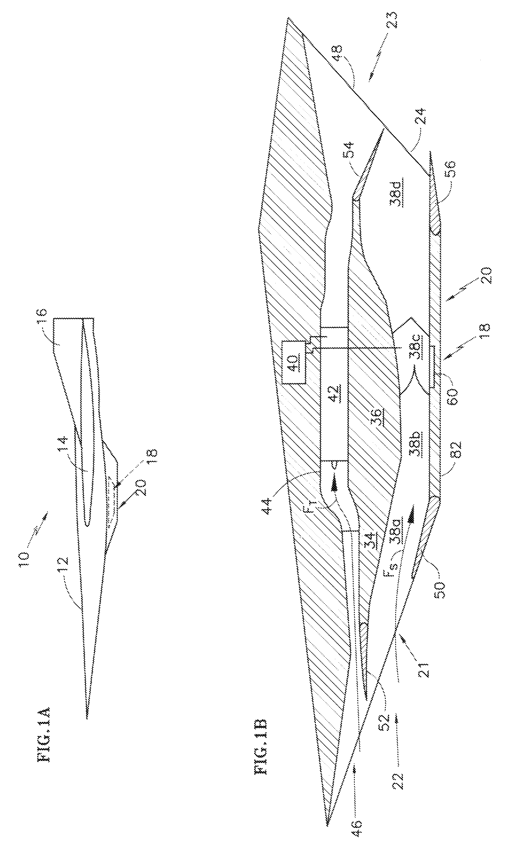
[0015]FIG. 1A schematically illustrates a vehicle 10. The disclosed embodiment schematically illustrates a hypersonic aircraft. Vehicles may be manned or unmanned, may be reusable or may be one-way such as warhead carrying missiles or disposable launch vehicles. The disclosed hypersonic propulsion system 18 is a gas turbine (subsonic and supersonic combustion) and supersonic ramjet engine (dual mode scramjet-DMSJ). It should be understood that other propulsion systems such a rocket based combined cycle engines and dual mode ramjet or scramjet engines or supersonics combustion ramjets (Scramjets) may also benefit herefrom.

[0016]The vehicle 10 generally includes a fuselage 12, a wing structure 14, and an empennage 16. The DMSJ propulsion system 18 is located within an engine package 20 defined in part by an underside of the fuselage 12. The engine package 20 is defined between a forward inlet 22 such as an intake structure and an aft outlet 23 such as an exhaust nozzle structure. The ...


PUM


Abstract

An electrical power generation system incorporates thermoelectric devices (TE Devices) for electrical power generation adjacent a flow path heat exchanger (HEX) adjacent to a vehicle flowpath structure such as a scramjet flow path to take advantage of the waste heat, high thermal gradients, and available, unused volume. A thermally conductive material communicates thermal energy from a vehicle external skin structure to the TE Device while a thermally conductive compliant material allows the TE Device to “float” with minimal mechanical stress.

Description

BACKGROUND OF THE INVENTION[0001]The present invention relates to a heat exchanger, and more particularly to a flowpath heat exchanger structure that incorporates thermoelectric devices (TE Devices) for electrical power generation.[0002]Hypersonic vehicles having fuel-cooled supersonic combustion ramjet (scramjet) dual mode engines enable missions such as time critical target service, global reach, responsive space launch, and space mission denial. Because of the propulsion system flowpath environmental conditions, both internally and externally, fuel cooling provides thermal management of the engine flowpath structure since it may not be practical to use air or radiation cooling at hypersonic operating conditions.[0003]Hypersonic vehicles will require electrical power for fuel pumps, drive actuators, and other propulsion and vehicle systems. Low speed systems, such as turbine based propulsion, can generate power while operational, but other power generation systems are required dur...

Claims


Application Information

Patent Timeline
IPC IPC(8): F02K7/14F25B21/02H01L35/30
CPCB64C1/38B64C30/00Y02T50/44H01L35/30B64D13/006Y02T50/40H10N10/13
Inventor JARMON, DAVID C.SILLENCE, MARK A.ATTRIDGE, PAULYAMANIS, JEAN
Owner AEROJET ROCKETDYNE OF DE
Why Eureka
Try Eureka