


Quick Research
Generate reliable direction feasibility study reports for your R&D in just a few steps.

Technical Q&A
Discover and master advanced knowledge NOW. Basics, ideas, possibilities, all at once.

Find Solutions
As an expert in R&D theories, this can generate solutions to your technical problems instantly.

Evaluate Feasibility
Analyze your overall solution with one click, know your potential R&D risks in advance.

Monitor Landscape
Get weekly tech updates, stay abreast of the latest tech innovations and key insights.
Exhaust Gas Purification Device
a technology of exhaust gas and purification device, which is applied in the direction of machines/engines, mechanical equipment, separation processes, etc., can solve the problems of large amount and large difference, and achieve the effect of preventing fuel consumption from being worse, high sensitivity, and high responsibility
- Summary
- Abstract
- Description
- Claims
- Application Information
AI Technical Summary
Benefits of technology
Problems solved by technology
Method used
Image


Examples
embodiment 1
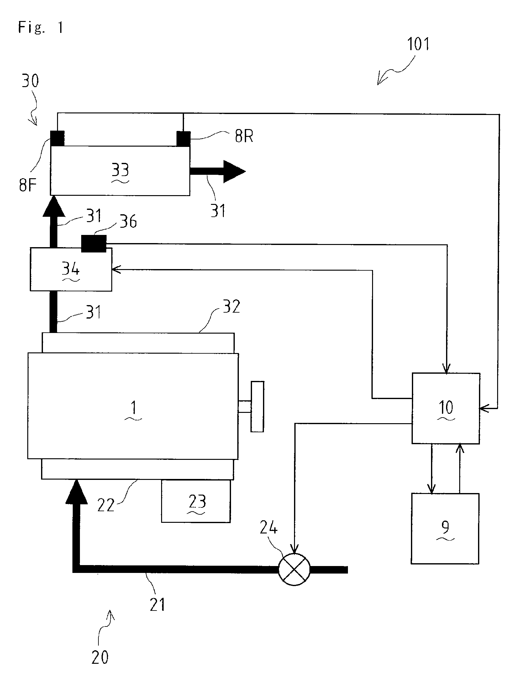
[0044]As shown in FIG. 1, with regard to an internal combustion engine such as a diesel engine, an induction system 20 is connected to one of sides (lower side in the drawing) of the engine main body 1, and an exhaust system 30 is connected to the other side (upper side in the drawing) thereof.
[0045]The induction system 20 comprises induction piping 21, an induction manifold 22 and a fuel pump 23. Air is inducted through the induction piping 21 and the induction manifold 22 into a cylinder of the engine main body 1 (a cylinder at inhalation process). Subsequently, at the time of finishing compression process of the cylinder, fuel is pressingly sent from the fuel pump 23 to a combustion chamber so that expansion process is performed following self-ignition combustion of fuel air mixture in the combustion chamber.
[0046]An induction throttle device 24 is disposed in the induction piping 21. Concretely, the induction throttle device 24 comprises a butterfly valve (not shown) and an actu...
embodiment 2
[0067]Next, explanation will be given on the exhaust gas purification device 102 of the second embodiment.
[0068]As shown in FIG. 3, with regard to the exhaust gas purification device 102, only the front sound pressure sensor 8F is disposed before, that is, at the upstream side of the DPF 33. Though the disposition position of the front sound pressure sensor 8F is not limited in the embodiment 1, the front sound pressure sensor 8F is disposed only at the upstream side of the DPF 33 in this embodiment, and only change of exhaust sound pressure at the upstream side of the DPF 33 is measured so as to recognize PM accumulation amount of the DPF 33.
[0069]That is because exhaust sound generated in the engine becomes to tend to be reflected following increase of PM accumulation amount of the DPF 33 so that exhaust sound pressure at the upstream side of the DPF 33 is changed. In FIG. 3, thick arrows indicate flow of air, and thin arrows indicate flow of signals.
[0070]Similarly to the embodim...
embodiment 3
[0076]Next, explanation will be given on the exhaust gas purification device 103 of the third embodiment.
[0077]As shown in FIG. 4, with regard to the exhaust gas purification device 103, only the sound pressure sensor 8R is disposed behind, that is, at the downstream side of the DPF 33. Though the disposition position of the front sound pressure sensor SF is not limited in the embodiment 1, the rear sound pressure sensor 8R is disposed only at the downstream side of the DPF 33 in this embodiment, and only change of exhaust sound pressure at the downstream side of the DPF 33 is measured so as to recognize PM accumulation amount of the DPF 33.
[0078]That is because exhaust sound generated in the engine becomes to tend to be screened by the DPF 33 following increase of PM accumulation amount of the DPF 33 so that exhaust sound pressure at the downstream side of the DPF 33 is changed. In FIG. 4, thick arrows indicate flow of air, and thin arrows indicate flow of signals.
[0079]The calcula...
PUM
| Property | Measurement | Unit |
|---|---|---|
| temperature | aaaaa | aaaaa |
| frequency | aaaaa | aaaaa |
| frequency | aaaaa | aaaaa |
Abstract
Description
Claims
Application Information
 - R&D Engineer
- R&D Manager
- IP Professional
- Industry Leading Data Capabilities
- Powerful AI technology
- Patent DNA Extraction
Browse by: Latest US Patents, China's latest patents, Technical Efficacy Thesaurus, Application Domain, Technology Topic, Popular Technical Reports.
© 2024 PatSnap. All rights reserved.Legal|Privacy policy|Modern Slavery Act Transparency Statement|Sitemap|About US| Contact US: help@patsnap.com