Open end ratchet wrench

Inactive Publication Date: 2009-06-18
ABUNAMEH HANI A
View PDF24 Cites 10 Cited by
  • Summary
  • Abstract
  • Description
  • Claims
  • Application Information

AI Technical Summary

Benefits of technology

[0013]According to a third embodiment of the invention designed for economic mass production; both two components of the wrench are made up of three flat metal plates riveted together (two casing parts and one core part). The three parts can be stamped out by dies and require no machining, thus reducing the production cost thereof. A semicircular tongue is stamped out into the inner face of one of the casing parts of the wrench to accommodate the groove in the rotating ratcheting inserts thus preventing their inward radial movement when the two head parts are in the open mode. The elongated tangentially protruding pin which is part of the second head frame component is rectangular with a plurality of notches and with a disengaging mechanism as described in the second embodiment of the invention. Two rectangular grooves disposed on the sides of the elongated pin with corresponding compatible tongues stamped out in the opposing inner faces of the casing plates control lateral movement of the pin as it slides into and out of the cavity in the second component. Two spring biased latches with wedged heads and teeth sized to fit into the peripheral ratchet teeth are disposed tangentially on the perimeters of the two head components. In the locked head condition, the latches are kept unengaged through outward pressure exerted against their heads by suitably shaped indentations deployed in the opposing semicircular frames, thus allowing free rotational movement of the ratchet wheel.
[0014]To disengage the wrench from the tightened nut, the locking mechanism of the two ratchet head components is released, and the ratchet pawl is disengaged to allow neutral bidirectional rotation of the of the wrench around the nut. The wrench is turned (by no more than 30 degrees) in either direction to align any adjoining line of adjacent inserts with the axis of the wrench, whereat the matching pins and corresponding holes in the adjoining sides of the insert elements are at right angles to the axis, thus allowing the separation of the semicircular head components each with a set of three inserts. When the two head components separate, the spring biased tangential latches are released to sink their teeth into the peripheral ratcheted teeth of the insert components thus preventing their rotational movement while the wrench head is in the open mode.

Problems solved by technology

For the system to operate properly, the ratcheting head required would be of an exaggerated size that will be awkward to handle in confined spaces.
In confined spaces, this can be highly problematic, and therefore place limits on the usefulness of the wrench.
The mechanism through which the two C-shaped collars containing the ratcheting inserts swing into position circumscribing the fastener from hinges attached to the C-shaped open head will fail to provide a perfect ratcheting wheel or a perfectly closed hexagonal socket, as this will be hindered by the thickness of the head member or the C-shaped collars as these swing around their hinges.
The disengagement of the wrench from the fastener will be problematic in confined spaces as the ratcheting wheel may have to be turned by up to 90 degrees to align the two parts of the ratcheting inserts to the open position for the swinging collars to open up.

Method used


Image

  • Open end ratchet wrench
  • Open end ratchet wrench
  • Open end ratchet wrench

Examples


second embodiment

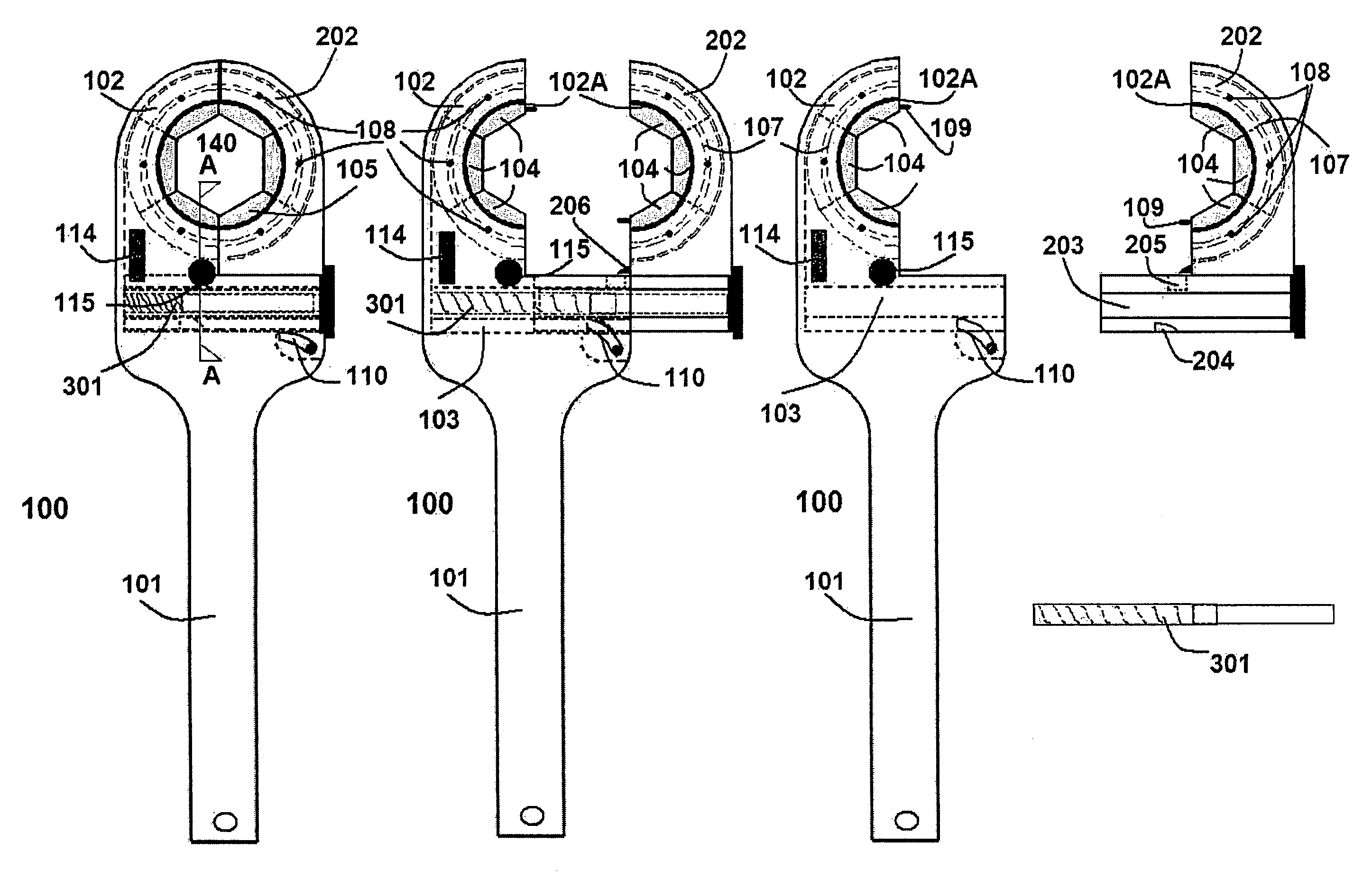
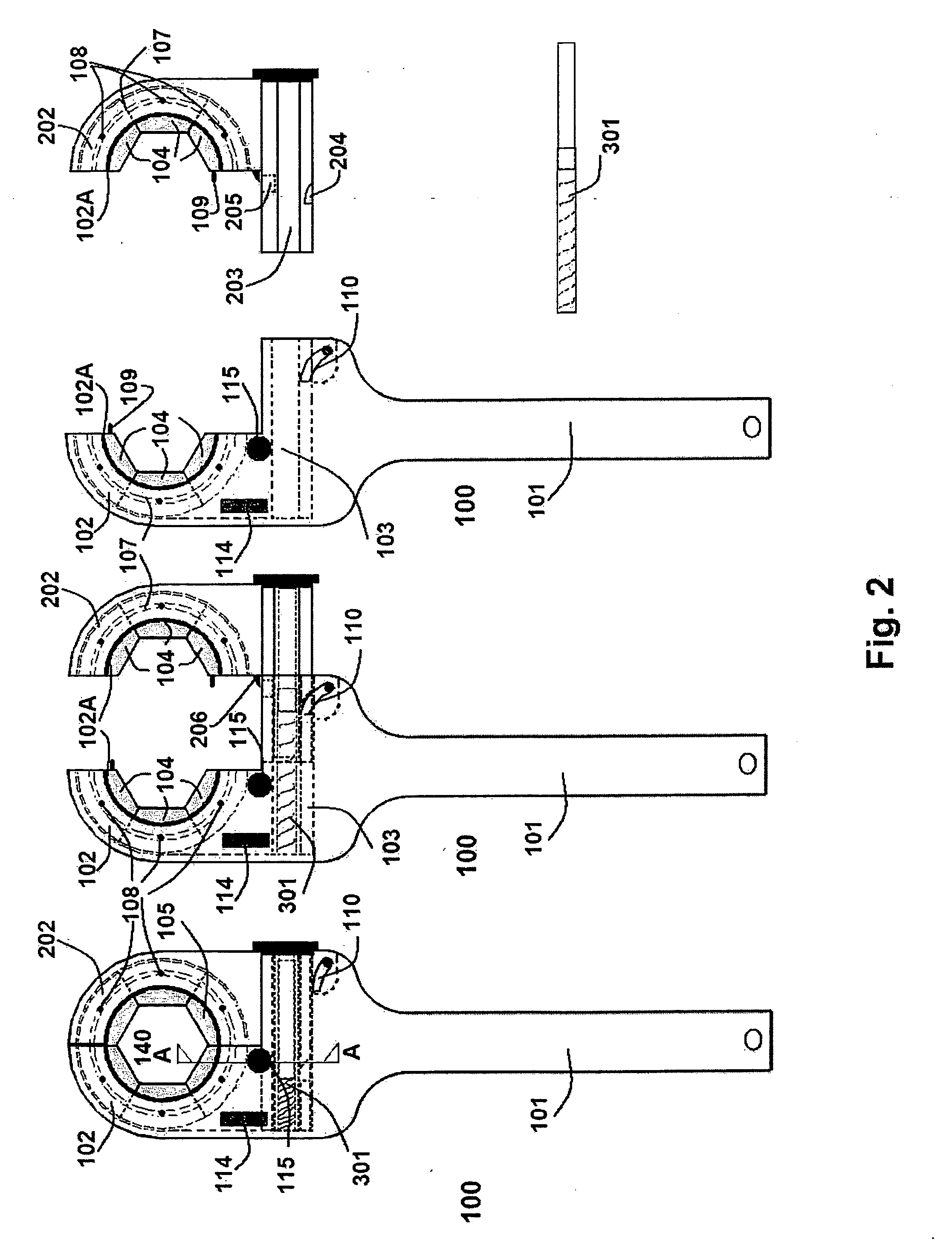
[0037]According to the invention as illustrated in FIG. 3, the elongated pin 203A protruding tangentially from the second semi-circular collar 202 has a solid cross-section (including the circular middle part). One side of the lower rectangular part of pin 203A has a plurality of notches along its entire length. Wheel (pinion) 302 with compatible notches and a biased torsion spring 303 engages the pin rack from below. Pinion 302 winds up its torsion spring when pin member 203A is pushed into slot 103A, and when the locking mechanism of the two semi-circular collars 102 and 202 is released, tends to push pin 203A in an outward direction, thus separating the two semi-circular collar head components and releasing the tie nut.

third embodiment

[0038]According to the invention designed for economic mass production as illustrated in FIGS. 9-12; both two components of the wrench are made up of three flat metal plates riveted together (two casing parts 410 and 430, and one core part 420). The three parts can be stamped out by dies and require no machining, thus reducing the production cost thereof. A semicircular tongue 408 is stamped out into the inner face of casing part 430 of the wrench head component to accommodate groove 107 in rotating ratcheting inserts 104 thus preventing their inward radial movement when the two head parts are in the open mode. Two rectangular grooves 409 disposed on the sides of the elongated rectangular pin 403 with corresponding compatible tongues 407 stamped out on the opposing inner faces of casing plates 410 and 430 control lateral movement of the pin as it slides into and out of the second component. Pin 403 is provided with a plurality of notches along the lower part of one side. A wheel (pi...

fourth embodiment

[0040]According to the invention, (not shown in the attached drawings and illustrations), the ratchet teeth are rectangular in shape engaged by a bi-directional pawl which can be set into active rotation clockwise or anti-clockwise, or into the neutral mode, through a switch handle connected thereto from the face of the wrench head.


PUM


Abstract

A ratchet wrench devised for torquing axially placed hexagonal nut fasteners on hydraulic or similar lines. The wrench is formed of two main components: The first component consists mainly of a straight elongated handle with a semi-circular collar head attached thereto opening to one side. The collar houses three identical metal inserts which when assembled therein form half a peripherally ratcheting wheel with half an axial inner hexagonally shaped socket of predetermined dimensions. The second main component comprises a second mirror-image semi-circular collar housing identical metal inserts, with a tangentially protruding pin member which slides into a slot disposed in the first component. The two components assembled together form a ratcheting wrench with a wheel having an axial hexagonal slot which circumscribes the fastener to be torqued. A spring-biased pawl disposed in the main component engages the ratchet wheel. Spring-biased latches and other mechanisms disposed within the wrench head provide smooth and fast engagement and disengagement of the two head components.

Description

I. BACKGROUND / FIELD OF THE INVENTION[0001]The present invention is used by plumbers and mechanics continuously engaged in assembling and removing hydraulic lines which require the handling of axially placed fasteners which can only be torqued with open-ended wrenches. Such tasks involve the frequent placement and removal of the wrench from the nut for the completion of a single operation. Such tasks, which are time wasting and exasperating, can be greatly facilitated if an efficient and practicable ratcheting wrench can be devised to deal with them.[0002]The present invention is designed to provide such a ratcheting wrench with a practicably sized head which makes it usable under most confined space conditions; which can be simply and smoothly opened and closed to fit perfectly around a nut fastener perpendicular to its axis, and functions as a standard ratcheting wrench without subjecting the fastener to damaging wear that may be caused by repeatedly clamping mechanisms. (U.S. Pat....

Claims


Application Information

Patent Timeline
IPC IPC(8): B25B13/08B25B13/46
CPCB25B13/14B25B13/481B25B13/463
Inventor ABUNAMEH, HANI A.
Owner ABUNAMEH HANI A
Why Eureka
Try Eureka