Apparatus for friction stir and friction stir processing

a technology of friction stir and apparatus, which is applied in the direction of soldering apparatus, manufacturing tools,auxillary welding devices, etc., can solve the problems of conventional friction stir joining and modification, blowing by, and causing blowing by, so as to suppress the occurrence of surface defects

Inactive Publication Date: 2009-06-18
HITACHI LTD
View PDF15 Cites 52 Cited by
  • Summary
  • Abstract
  • Description
  • Claims
  • Application Information

AI Technical Summary

Benefits of technology

[0013]According to the present invention, it is possible to suppress an occurrence of a surface defect in an area processed by the friction stir.

Problems solved by technology

In case of the groove for fitting the piston ring, for example, an alumite layer inferior in smoothness causes compressed gas to escape from the combustion chamber to the crankcase, that is, it causes so-called blow-by.
However, joining and modification by a conventional friction stir involve problems.
In case of the above-mentioned piston ring, there is a possibility that the blow-by will be caused by this key hole.
However, this technology also involves a problem.
Under this condition, it is difficult to secure sufficient width and depth of a modified area.
In addition, it is required to use a tool of small diameter and this shortens the life of the tool.
In this method, the dolly block must be prepared for each piston and this increases the production cost.

Method used


Image

  • Apparatus for friction stir and friction stir processing
  • Apparatus for friction stir and friction stir processing
  • Apparatus for friction stir and friction stir processing

Examples


first embodiment

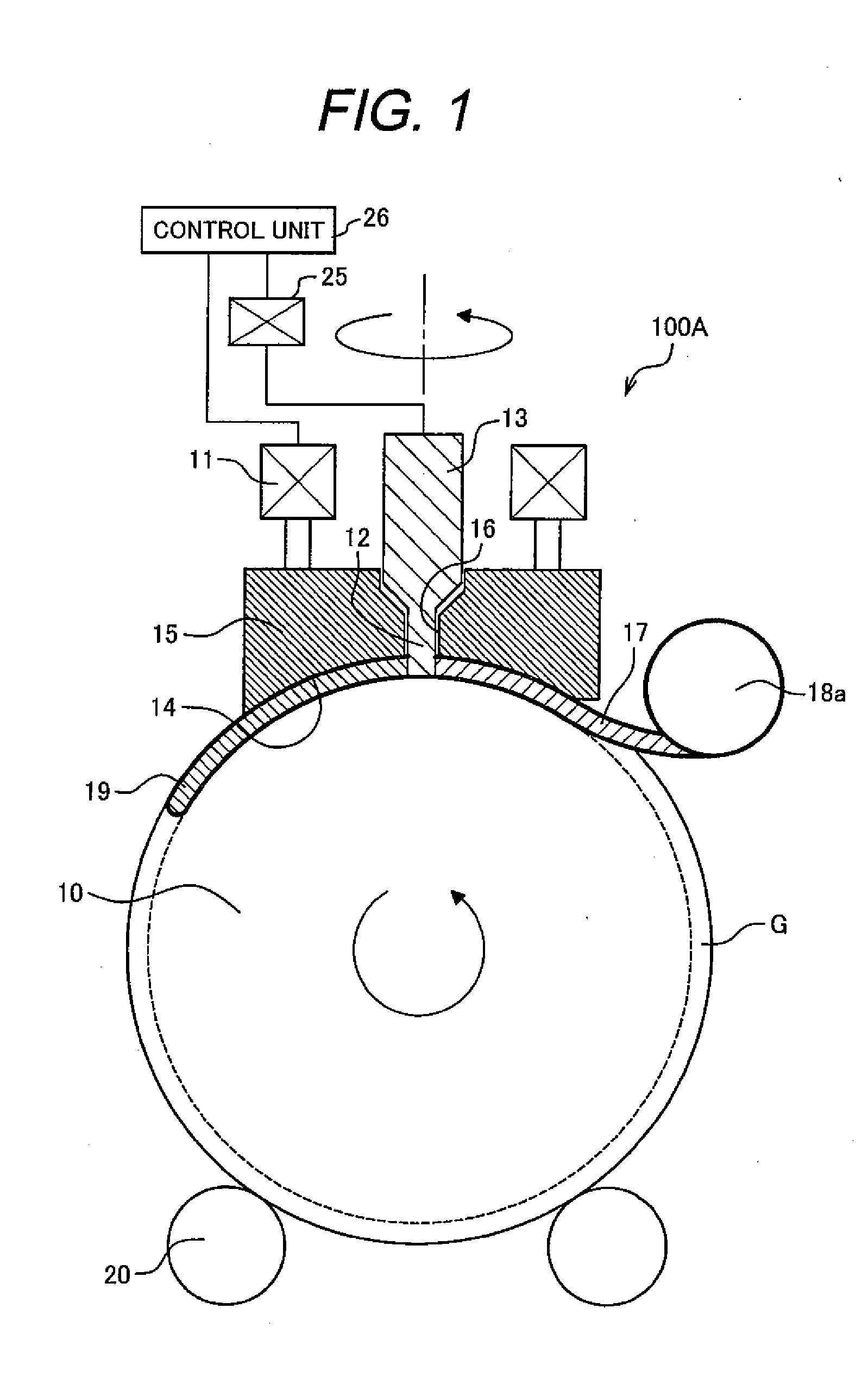
[0037]FIG. 1 is a sectional view schematically illustrating a structure of an apparatus for a friction stir in a first embodiment of the present invention. An apparatus 100A for the friction stir is so structured that a friction stir processing is carried out so that an arc is drawn along a curved circumferential surface of a columnar or cylindrical work 10. The work 10 is supported on backing rollers 20 and is rotated on a central axis by a motor (not shown) for a rotary table or the like. In the work 10, a ring-like groove G is formed and the apparatus 100A for the friction stir rotates the work 10 and carries out the friction stir processing along the groove G.

[0038]The apparatus 100A for the friction stir includes a tool 13 having a columnar tip-side part (hereafter, referred to as “pin”) 12, a rotating and pressing unit 25 having the function of a rotating unit for rotating a tool 13 on the central axis and the function of a first pressing unit for pressing the pin 12 against t...

second embodiment

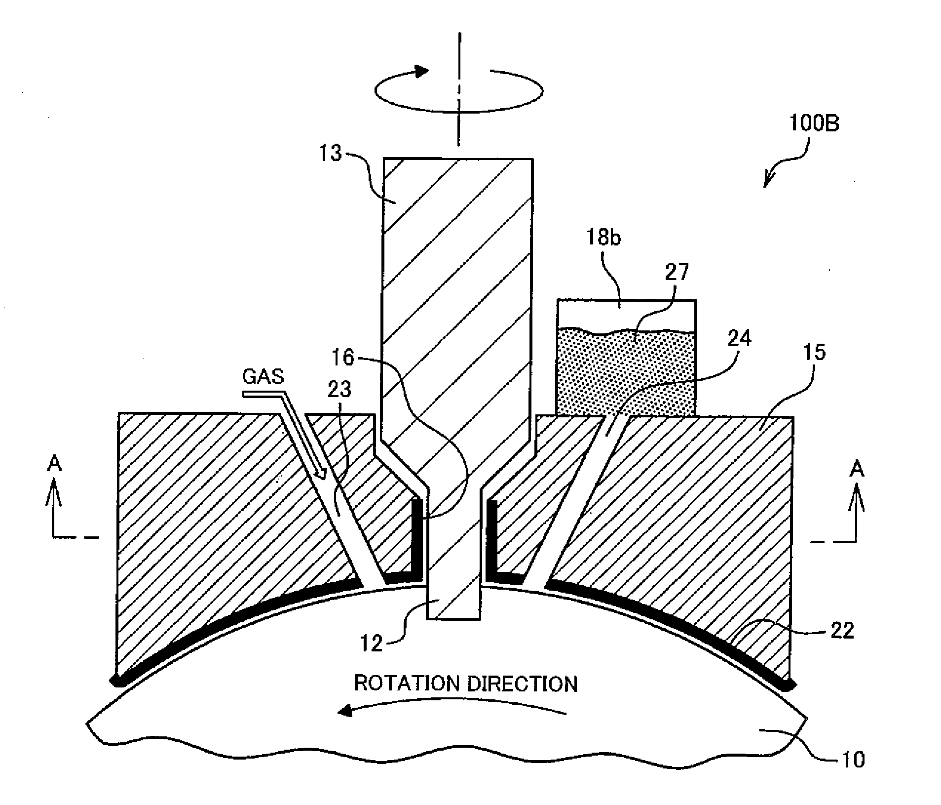
[0059]FIG. 3A is a sectional view schematically illustrating a structure of an apparatus 100B for a friction stir in a second embodiment and FIG. 3B is a sectional view taken along line A-A of FIG. 3A. In this apparatus 100B for the friction stir, a hard film 22 is formed on the sliding surface of the retaining jig 15 for suppressing wear caused by friction with the work 10. Examples of the material favorably used for the hard film 22 include diamond-like carbon, titanium nitride, chromium nitride, and the like though not limited to these materials. Any material can be used for the hard film 22 as long as the Vickers hardness Hv of the material is not less than approximately 1000. It is desirable that a coefficient of friction of the hard film 22 should be low and the coefficient of friction of not more than 0.1 is more desirable.

[0060]It is desirable that a pattern of convexes and concaves (not shown), such as dimples or grooves, should be formed on the sliding surface of the retai...

third embodiment

[0064]FIG. 4 is a sectional view schematically illustrating an apparatus 100C for a friction stir in a third embodiment. This apparatus 100C for the friction stir is different from the above-mentioned apparatus 100A for the friction stir in that: a conventionally commonly used tool 13a is used in place of the tool 13 and a straight pipe-like tool insertion hole 16a is formed in the retaining jig 15 for inserting this tool 13a. The conventionally commonly used tool is so structured that a columnar shoulder 21 is provided with a short columnar pin 12a smaller in a diameter than and coaxially with the shoulder 21.

[0065]When the friction stir processing in the above-mentioned first to third processing modes of the first embodiment is carried out using the tool 13a, the following usually takes place when the tool 13a is pulled out of the work 10: the shoulder 21 gets away from the work 10 first and a key hole is produced. For this reason, the apparatus 100C for the friction stir is used ...


PUM

PropertyMeasurementUnit
frequencyaaaaaaaaaa
diameteraaaaaaaaaa
diameteraaaaaaaaaa

Abstract

An apparatus for a friction stir and a friction stir processing of the present invention suppress an occurrence of a surface defect in an area processed by the friction stir. The apparatus for the friction stir includes a tool having a columnar tip-side part, a rotating unit for rotating the tool on a central axis, a first pressing unit for pressing a tip of the tool rotated by the rotating unit against a work, a jig having a tool insertion hole into which the tip-side part of the tool is inserted so that the tip-side part of the tool is encircled around the jig, a second pressing unit for slidably pressing the jig against the work, and a press control unit for controlling the first pressing unit so that the tip-side part of the tool is gradually pulled out of the work by the first pressing unit while moving the tool and the jig relative to the work, in a state that the tool is rotated by the rotating unit and the tip of the tool has been sunk into the work to a predetermined depth by the first pressing unit.

Description

BACKGROUND OF THE INVENTION[0001]1Field of the Invention[0002]The present invention relates to an apparatus for a friction stir and a friction stir processing.[0003]2. Description of Related Art[0004]As a method for butt joining members, a friction stir welding (FSW) method is known. (Refer to Document 1 (Published Japanese Translation of PCT Application No. Hei 07-505090), for example.) In this method, members are joined together in solid state by taking the following procedure: a rotating tool is pressed against a seam; frictional heat produced between the tool and the members at this time is utilized to soften the members in proximity to the tool; and the tool is rotated and moved along the seam between the members. As one of the applications of this friction stir welding, for example, the following modification treatments are carried out using the same process as in the friction stir welding: the modification of an aluminum cast, the development of super plasticity by microstruc...

Claims


Application Information

Patent Timeline
Patent Type & Authority Applications(United States)
IPC IPC(8): B23K20/12
CPCB23K20/126B23K20/128B23K2203/10B23K2201/003B23K20/14B23K2101/003B23K2103/10
Inventor OKAMOTO, KAZUTAKAPARK, SEUNG HWANHIRANO, SATOSHI
Owner HITACHI LTD
Why Eureka
Try Eureka