Oil-repellent film forming method, motor manufacturing method and motor
a technology of oil-repellent film and manufacturing method, which is applied in the direction of sliding contact bearings, mechanical equipment, electric/magnetic/electromagnetic heating, etc., can solve the problems of time-consuming and laborious, reducing productivity, and large production facilities, so as to reduce thermal deformation of metallic parts, rapid cure of adhesive agents interposed, and quick performance of tasks
- Summary
- Abstract
- Description
- Claims
- Application Information
AI Technical Summary
Benefits of technology
Problems solved by technology
Method used
Image

Examples
first embodiment
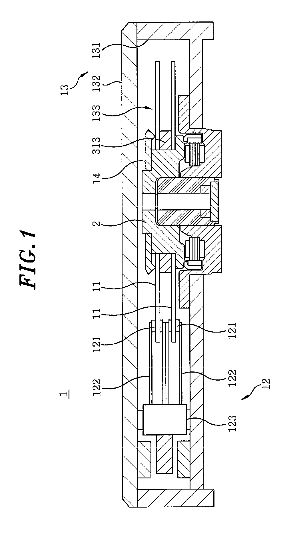
[0049]FIG. 1 is a vertical section view showing a storage disk drive apparatus 1 in accordance with the present invention, which includes an electric spindle motor (hereinafter referred to as a “motor”). The storage disk drive apparatus 1 includes storage disks 11 for storing information; an access unit 12 for reading or writing (reading / writing or reading only) information from / to the storage disks 11; an electric motor 2 for rotating the storage disks 11; and a housing 13 for receiving the storage disks 11, the access unit 12 and the motor 2 within an internal space thereof to isolate them from the outside.
[0050]The housing 13 includes a first housing member 131 of cup-like shape having an opening formed in its upper portion and an inner bottom surface on which the motor 2 and the access unit 12 are mounted; and a second housing member 132 of plate-like shape for covering the opening of the first housing member 131 to define an internal space 133. In the storage disk drive apparat...
second embodiment
[0096]Next, description will be made on the task of affixing the base plate 43 to the thrust yoke 44 in the motor 2a shown in FIG. 11 according to the present invention. FIG. 19 is a flow chart illustrating the process through which the base plate 43 is affixed to the thrust yoke 44. FIG. 20 is a view partially showing the cross-section of the base plate 43 taken along a plane containing the central axis J1 of the motor 2a.
[0097]First, a thermally curable adhesive agent 71 is applied on the outer periphery of the bottom surface 4331 of the recess portion 433 in the base plate 43 (namely, on the annular region located radially outward of the through-hole 4332) (step S21). The adhesive agent 71 is of a single component capable of being cured rapidly, and is what is called as a completely epoxy-based adhesive agent that only includes an epoxy-based substance as an adhesive component. Use of the single-component adhesive agent helps to simplify the manufacturing process of the motor 2a...
third embodiment
[0121]With reference to FIG. 32, description will be made on the task of sealing with a resin the affixing portion 81 of the board 8 attached to the base plate 43 in the motor 2a shown in FIG. 11 according to the Prior to performing the sealing task, the lead lines of the stator 42 fixed to the holder 432 of the base plate 43 are led via the bush 45 inserted into the through-hole 4332, and are bonded to the board 8 disposed in the board attachment region 4611 in the rear surface 461 (the surface facing away from the stator 42) of the base plate 43 (see FIG. 1) (step S61).
[0122]Then, as shown in FIG. 26, the base plate 43 and the stator 42 are held in place in a state that the stator 42 faces downward, so that the stator 42 and the holder 432 of the base plate 43 is located in the opening of the holder portion 61. The induction coil 92 is arranged above and near the rear surface 461 (the upwardly facing surface in FIG. 26) of the base plate 43.
[0123]An AC current with a frequency of...
PUM
| Property | Measurement | Unit |
|---|---|---|
| Fraction | aaaaa | aaaaa |
| Frequency | aaaaa | aaaaa |
| Force | aaaaa | aaaaa |
Abstract
Description
Claims
Application Information
 - R&D
- Intellectual Property
- Life Sciences
- Materials
- Tech Scout
- Unparalleled Data Quality
- Higher Quality Content
- 60% Fewer Hallucinations
Browse by: Latest US Patents, China's latest patents, Technical Efficacy Thesaurus, Application Domain, Technology Topic, Popular Technical Reports.
© 2025 PatSnap. All rights reserved.Legal|Privacy policy|Modern Slavery Act Transparency Statement|Sitemap|About US| Contact US: help@patsnap.com