
Oil-repellent film forming method, motor manufacturing method and motor

a technology of oil-repellent film and manufacturing method, which is applied in the direction of sliding contact bearings, mechanical equipment, electric/magnetic/electromagnetic heating, etc., can solve the problems of time-consuming and laborious, reducing productivity, and large production facilities, so as to reduce thermal deformation of metallic parts, rapid cure of adhesive agents interposed, and quick performance of tasks

Inactive Publication Date: 2011-07-05
NIDEC CORP
View PDF15 Cites 3 Cited by
  • Summary
  • Abstract
  • Description
  • Claims
  • Application Information

AI Technical Summary

Benefits of technology

The present invention provides a technique for quickly and cost-effectively forming an oil-repellent film on motor parts, fixing them with adhesive, and pre-heating a circuit board to seal the bonding portion. This is done without using a traditional oven or hot plate. The technique also reduces deformation of the parts caused by heating. The use of induction heating and an AC current with a frequency of about 5 to 100 kHz makes it possible to quickly perform these tasks while reducing thermal deformation and allowing for the use of a low-price circuit.

Problems solved by technology

However, in case the parts of a motor applied with an oil-repellent agent are heated within an oven, it is time-consuming to elevate the temperature.
This reduces the productivity and becomes an obstacle in automating a manufacturing process.
Moreover, the production facilities grow large.
Similarly, when the parts of a motor are affixed using a thermally curable adhesive agent, the task of heating them within an oven is time-consuming and becomes an obstacle in automating a manufacturing process.
However, it also takes a large amount of time to pre-heat the base portion using a hot plate.
Consequently, a steep temperature variation occurs between the interior region and the surface region of the parts, which leads to a thermal deformation of the parts (namely, distortion or dimensional change in the parts).

Method used

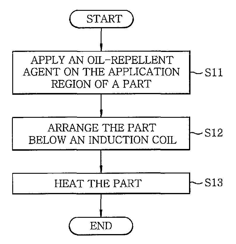

Image

  • Oil-repellent film forming method, motor manufacturing method and motor
  • Oil-repellent film forming method, motor manufacturing method and motor
  • Oil-repellent film forming method, motor manufacturing method and motor

Examples


first embodiment

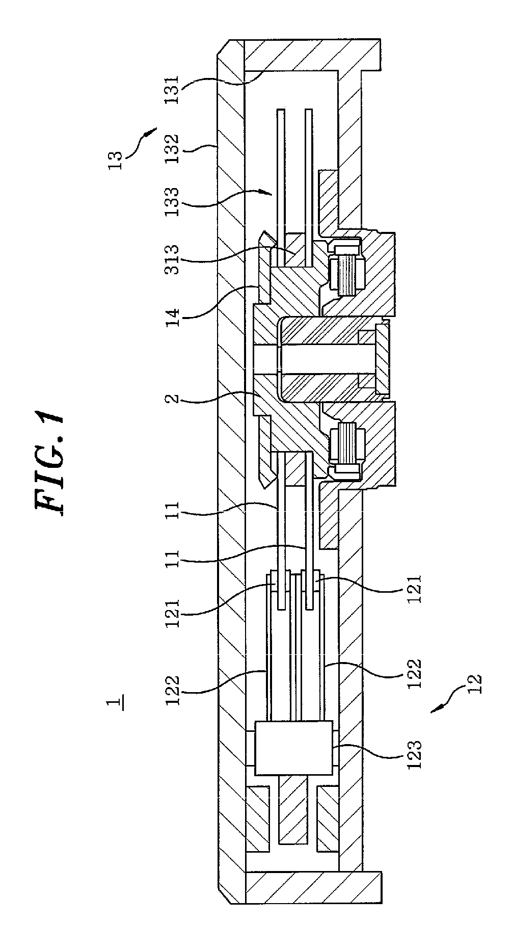
[0049]FIG. 1 is a vertical section view showing a storage disk drive apparatus 1 in accordance with the present invention, which includes an electric spindle motor (hereinafter referred to as a “motor”). The storage disk drive apparatus 1 includes storage disks 11 for storing information; an access unit 12 for reading or writing (reading / writing or reading only) information from / to the storage disks 11; an electric motor 2 for rotating the storage disks 11; and a housing 13 for receiving the storage disks 11, the access unit 12 and the motor 2 within an internal space thereof to isolate them from the outside.

[0050]The housing 13 includes a first housing member 131 of cup-like shape having an opening formed in its upper portion and an inner bottom surface on which the motor 2 and the access unit 12 are mounted; and a second housing member 132 of plate-like shape for covering the opening of the first housing member 131 to define an internal space 133. In the storage disk drive apparat...

second embodiment

[0096]Next, description will be made on the task of affixing the base plate 43 to the thrust yoke 44 in the motor 2a shown in FIG. 11 according to the present invention. FIG. 19 is a flow chart illustrating the process through which the base plate 43 is affixed to the thrust yoke 44. FIG. 20 is a view partially showing the cross-section of the base plate 43 taken along a plane containing the central axis J1 of the motor 2a.

[0097]First, a thermally curable adhesive agent 71 is applied on the outer periphery of the bottom surface 4331 of the recess portion 433 in the base plate 43 (namely, on the annular region located radially outward of the through-hole 4332) (step S21). The adhesive agent 71 is of a single component capable of being cured rapidly, and is what is called as a completely epoxy-based adhesive agent that only includes an epoxy-based substance as an adhesive component. Use of the single-component adhesive agent helps to simplify the manufacturing process of the motor 2a...

third embodiment

[0121]With reference to FIG. 32, description will be made on the task of sealing with a resin the affixing portion 81 of the board 8 attached to the base plate 43 in the motor 2a shown in FIG. 11 according to the Prior to performing the sealing task, the lead lines of the stator 42 fixed to the holder 432 of the base plate 43 are led via the bush 45 inserted into the through-hole 4332, and are bonded to the board 8 disposed in the board attachment region 4611 in the rear surface 461 (the surface facing away from the stator 42) of the base plate 43 (see FIG. 1) (step S61).

[0122]Then, as shown in FIG. 26, the base plate 43 and the stator 42 are held in place in a state that the stator 42 faces downward, so that the stator 42 and the holder 432 of the base plate 43 is located in the opening of the holder portion 61. The induction coil 92 is arranged above and near the rear surface 461 (the upwardly facing surface in FIG. 26) of the base plate 43.

[0123]An AC current with a frequency of...


PUM

PropertyMeasurementUnit
frequencyaaaaaaaaaa
frequencyaaaaaaaaaa
temperatureaaaaaaaaaa

Abstract

A method is for forming an oil-repellent film on a metallic part in a dynamic fluid pressure bearing mechanism used for a motor. The method includes applying a flowable oil-repellent agent on an application region of the metallic part; arranging an induction coil in the vicinity of the metallic part; and affixing the oil-repellent agent onto the metallic part by applying an induction heating to the metallic part by supplying an AC current with a frequency of about 5 to 100 kHz to the induction coil. Further, a motor includes a dynamic fluid pressure bearing mechanism including a metallic part on which an oil-repellent film is formed by the above method; a stator unit; and a rotor unit supported by the dynamic fluid pressure bearing mechanism in a manner rotatable with respect to the stator unit.

Description

FIELD OF THE INVENTION[0001]The present invention relates to a technique of manufacturing a motor; and, more particularly, to a technique of forming an oil-repellent film on the parts of a motor, a technique of assembling the parts of a motor with an adhesive agent and a technique of sealing a bonding portion of a circuit board in a motor.BACKGROUND OF THE INVENTION[0002]Conventionally, in case a dynamic fluid pressure bearing mechanism is employed in a spindle motor (hereinafter referred to as a “motor”), the boundary between a lubricant filled in the dynamic fluid pressure bearing mechanism and an ambient air is formed within a gap of tapering shape to prevent leakage of the lubricant. In the dynamic fluid pressure bearing mechanism of this structure, it is typical that an oil-repellent agent is applied on portions close to a lubricant level to thereby form an oil-repellent film. Japanese Patent Application Publication No. 2004-289957A discloses a technique of forming an oil-repel...

Claims


Application Information

Patent Timeline
Patent Type & Authority Patents(United States)
IPC IPC(8): H02K5/16
CPCF16C17/10F16C33/107H02K5/1675F16C41/008F16C33/74Y10T29/49009
Inventor NARITA, TAKAYUKIKONISHI, YUKI
Owner NIDEC CORP
Learn More