
Image processing device, image display system, image processing method and program therefor

a technology of image display system and image processing method, which is applied in the direction of television system, color signal processing circuit, instruments, etc., can solve the problem that the motion blur restraining effect cannot be sufficiently achieved within one frame, and the high voltage applied to accelerate the response speed of liquid crystal may not be applied. the effect of reducing the cost of display device and reducing the cost of the display devi

Inactive Publication Date: 2009-06-18
SONY CORP
View PDF8 Cites 26 Cited by
  • Summary
  • Abstract
  • Description
  • Claims
  • Application Information

AI Technical Summary

Benefits of technology

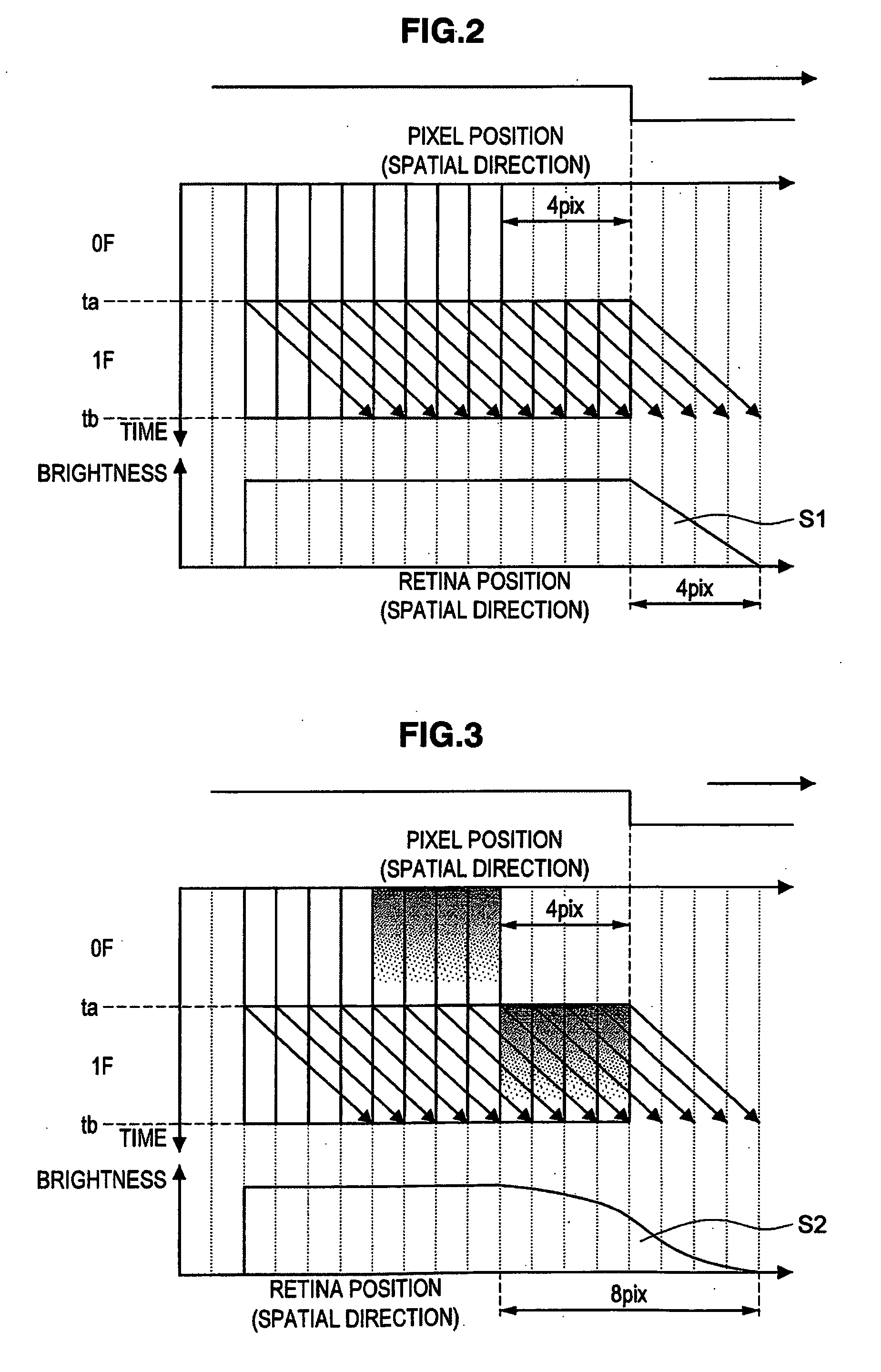
[0010]Recently, a double-speed operation technique has been developed for displaying image data on the LCD, by time-dividing a frame to be displayed in order to reduce the Eye-Trace Integration effect, and obtaining an interpolated image between frames based on a motion vector of an input image in order to increase the motion picture display frequency using a plurality of sub-fields.
[0012]The present invention has been made in consideration of the above issues. It is desirable to restrain an increase in cost, to reduce an Eye-Trace Integration effect, to improve a response characteristic of image display in all tone variations, and to restrain the motion blur, in an image processing device which processes externally input image data and outputs it to a hold-type display device, an image display system including the processing device, an image processing method and a program therefor.
[0030]As described above, according to the image processing device, image display system, image processing method and program of the present invention, in what is so-called a hold-type display device, it is possible to restrain the motion blur, such as blurring in the leading edge, tailing in the trailing edge, delay in a perception position, in a moving object by an Eye-Trace Integration effect, thus improving quality of a moving image. There is a need for a change in the display device itself in the double-speed operation. However, according to the present invention, there is no need to make any change in the display device, thus no resulting in an increase in cost of the display device. Further, the motion blur can sufficiently be restrained in the tone variation in a region, other than the half tone region, that may not be improved using the overdrive technique. Particularly, in the display device using the display element with a slow response speed, the greater the difference of the response times due to the tone variation, resulting in a great restraining effect of the motion blur.
[0031]According to the embodiments of the present invention, it is possible to restrain an increase in cost, to reduce the Eye-Trace Integration effect, to improve a response characteristic of image display in all tone variations, and to restrain the motion blur, in an image processing device which processes externally input image data and outputs it to a hold-type display device, an image display system including the processing device, an image processing method and a program therefor.

Problems solved by technology

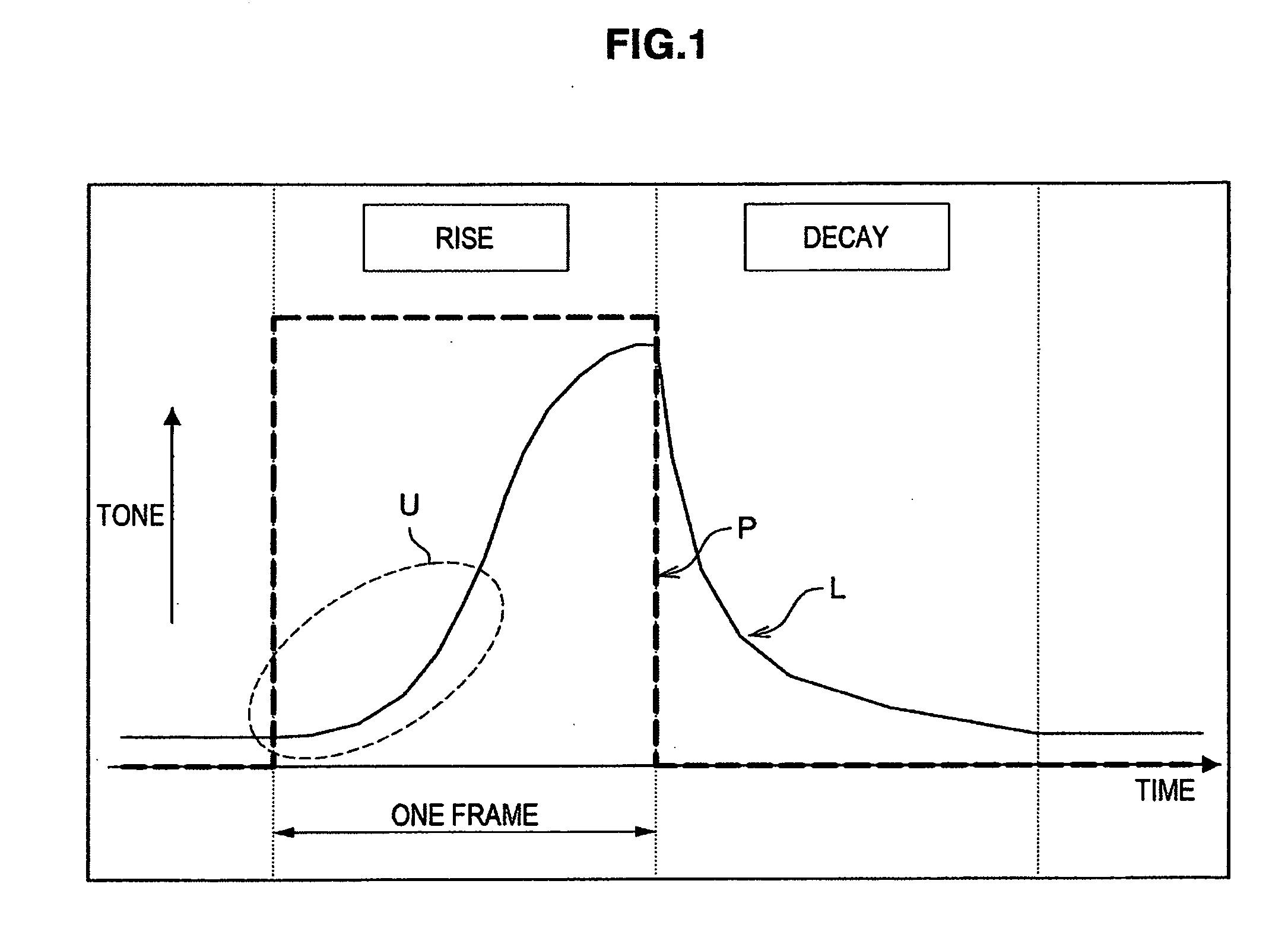
However, an issue in the overdrive technique is that a sufficiently high voltage for accelerating the response speed of the liquid crystal may not be applied, because of the limit of the applicable voltage range in the liquid crystal.
As a result, the motion blur restraining effect may not sufficiently be attained, for example, when a target voltage for a black display or a white display is near the limit of the voltage range (in the case of the tone variation in a high tone range or a low tone range).
Thus, an issue is that a specified brightness transition may not be attained within one frame in consideration of the response speed of the liquid crystal using only the overdrive technique.
This may result an issue of an insufficient charge, an increase in the number of terminals of IC or connector, an increase in the substrate area, heat generation, an increase in EMI (Electro Magnetic Interference), an increase in cost.

Method used


Image

  • Image processing device, image display system, image processing method and program therefor
  • Image processing device, image display system, image processing method and program therefor
  • Image processing device, image display system, image processing method and program therefor

Examples


Embodiment Construction

[0055]Hereinafter, preferred embodiments of the present invention will be described in detail with reference to the appended drawings. Note that, in this specification and the appended drawings, structural elements that have substantially the same function and structure are denoted with the same reference numerals, and repeated explanation of these structural elements is omitted.

Improvement of Motion Blur

[0056]Before explaining the preferred embodiments of the present invention, the present inventors first explain why the present inventors have reached an image processing device according to the present invention as an improvement device for a motion blur in a hold-type display device, such as a liquid crystal display device or the like.

[0057]As described above, in the hold-type display device, an object in motion may result in a motion blur, such as a blur in the leading edge, tailing in the trailing edge, and a delay in a perception position. In related art, the cause of the above...


PUM


Abstract

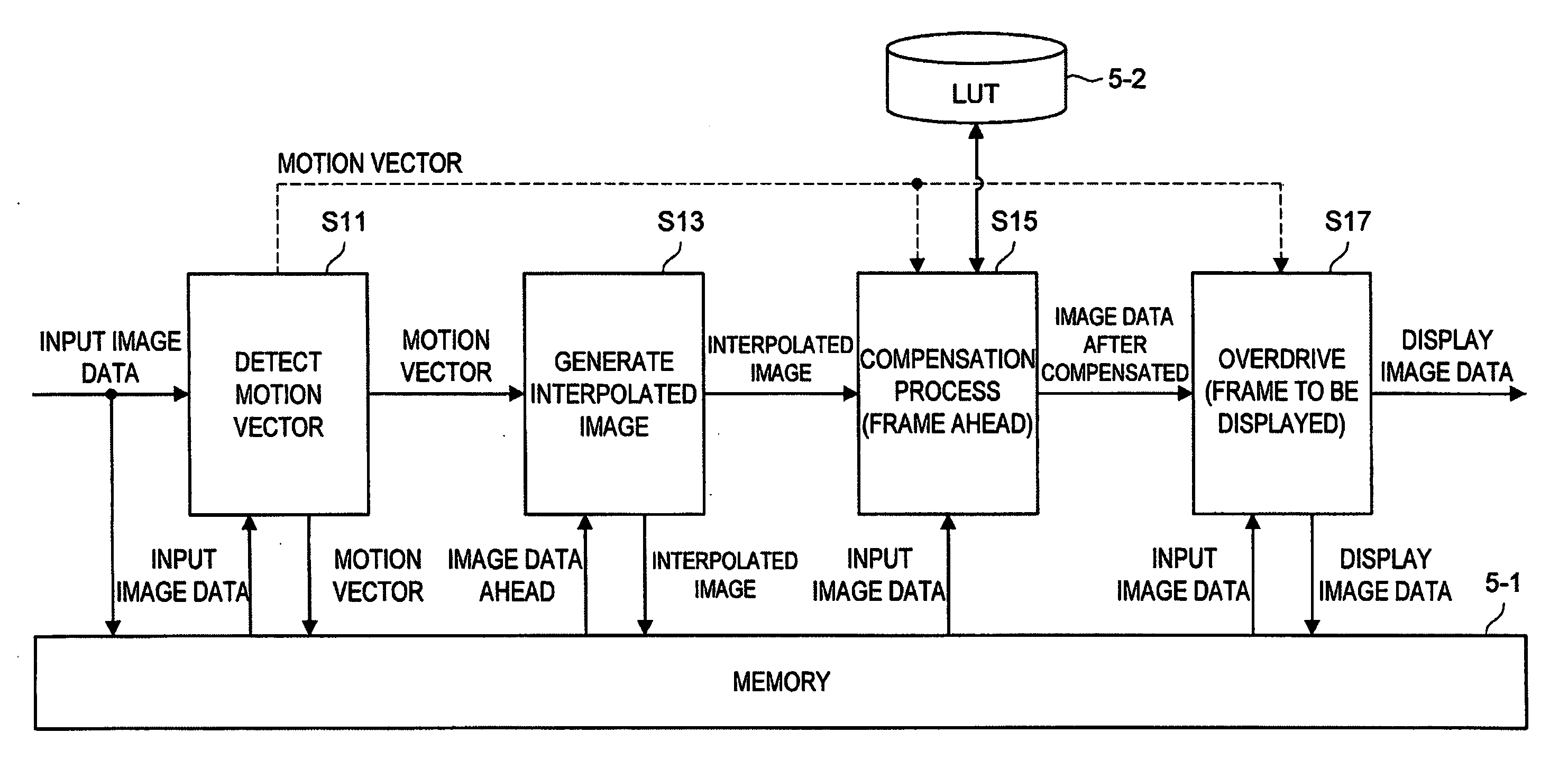
An image processing device according to the present invention includes a motion vector detecting unit, a response time information storage unit, a compensation processing unit and an output unit. The motion vector detecting unit detects a motion vector of image data. The response time information storage unit stores response time information representing a time since a driving voltage is applied to a display device until an image with a corresponding tone is displayed in association with a tone variation value. The compensation processing unit compensates a pixel value in image data for each pixel in a frame that is one frame ahead of a frame to be displayed, based on the image data, the motion vector and the response time information. The output unit outputs the image data after compensated by the compensation processing unit to the display device.

Description

CROSS-REFERENCE TO RELATED APPLICATION[0001]The present invention contains subject matter related to Japanese Patent Application JP 2007-326342 filed in the Japan Patent Office on Dec. 18, 2007, the entire contents of which being incorporated herein by reference.BACKGROUND OF THE INVENTION[0002]1. Field of the Invention[0003]The present invention relates to an image processing device which processes externally input image data and outputs it to a hold-type display device, an image display system including the processing device, an image processing method and a program therefor.[0004]2. Description of the Related Art[0005]In recent years, flat panel displays like LCDs (Liquid Crystal Display) have widely been spread, in place of CRTs (Cathode Ray Tube).[0006]In motion display, unlike an impulse-type display device, such as a CRT, a hold-type display device, such as LCD, keeps displaying all pixels constituting an image page, for a period of time since an instruction of displaying a p...

Claims


Application Information

Patent Timeline
Patent Type & Authority Applications(United States)
IPC IPC(8): H04N5/14H04N5/66
CPCG09G3/3648G09G2320/0252G09G2320/0261G09G2320/0271H04N5/21G09G2340/16H04N5/142H04N5/144H04N5/145G09G2320/106
Inventor ARASHIMA, KENJI
Owner SONY CORP
Learn More