Polishing end point detection method, polishing end point detection apparatus and polishing apparatus

a detection method and polishing technology, applied in the direction of optical radiation measurement, lapping machines, instruments, etc., can solve the problems of preventing the accurate detection of unable to receive reflected laser light, and difficult to detect the polishing end point from the change in interference color, etc., to achieve accurate detection, fast detection, and bright and saturation of the surface

Active Publication Date: 2009-06-18
EBARA CORP
View PDF3 Cites 14 Cited by
  • Summary
  • Abstract
  • Description
  • Claims
  • Application Information

AI Technical Summary

Benefits of technology

[0039]According to one aspect of the present invention, because the brightness and the saturation of the surface decrease or increase abruptly at the polishing end point (i.e., when the upper layer is removed), the polishing end point can be detected accurately based on the changes in the brightness and the saturation of the surface that is being polished.
[0040]According to another aspect of the present invention, because the polishing end point is determined by monitoring the change in at least one of the phase difference Δ and the amplitude ratio ψ, it is not necessary to analyze the film thickness and the index of refraction. Therefore, the polishing end point can be quickly detected.

Problems solved by technology

Therefore, it is difficult to detect the polishing end point from the change in the interference color using the spectroscopic polishing end point detection method.
However, this method has the following problems.
Such a periodical change in intensity of the laser light prevents accurate detection of the polishing end point.
As a result, the reflected laser light cannot be received.
However, analyzing of the index of refraction and the thickness of the film is complex.
Therefore, a relatively long period of time is required for determining the film thickness.

Method used


Image

  • Polishing end point detection method, polishing end point detection apparatus and polishing apparatus
  • Polishing end point detection method, polishing end point detection apparatus and polishing apparatus
  • Polishing end point detection method, polishing end point detection apparatus and polishing apparatus

Examples


Embodiment Construction

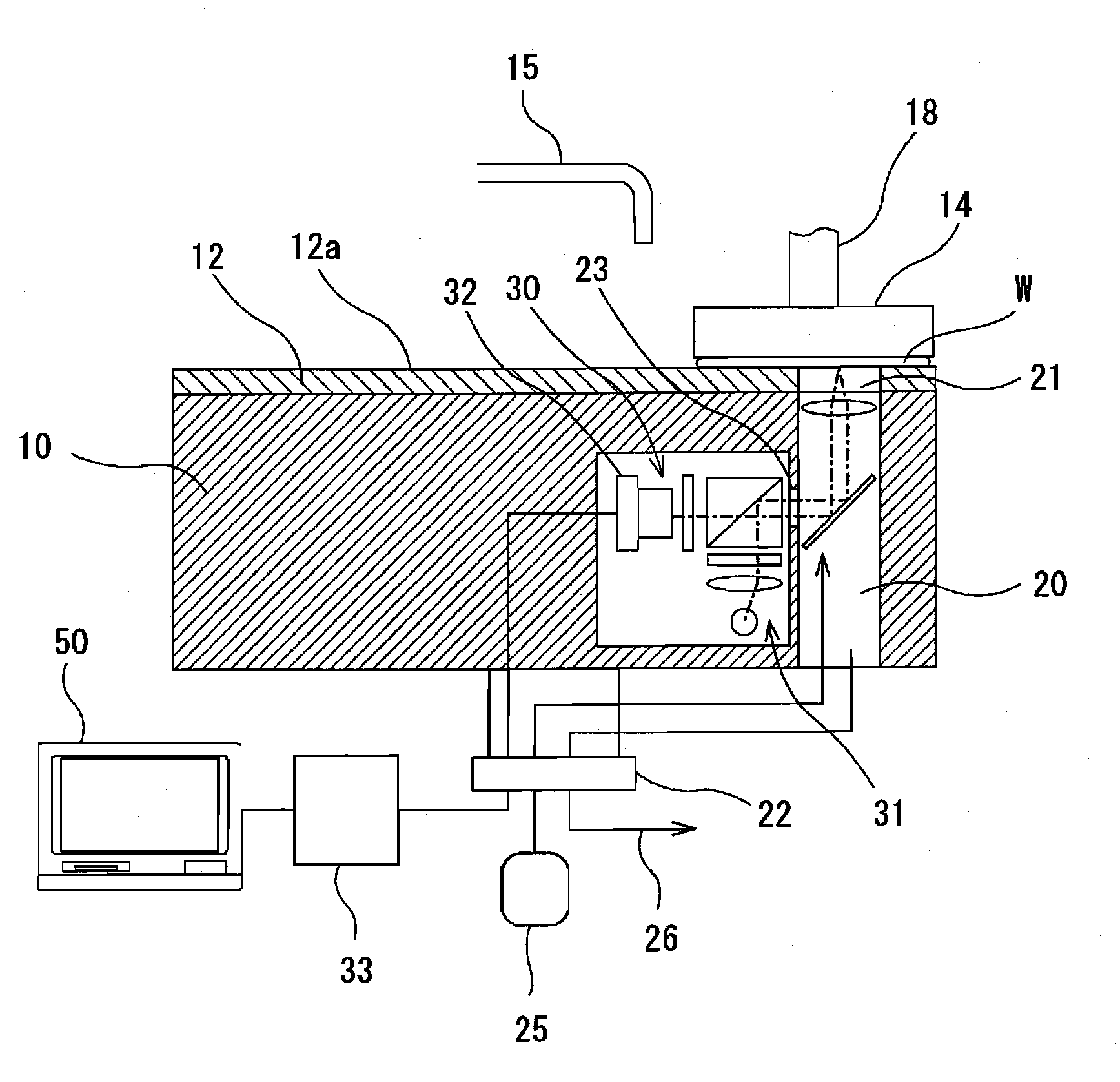
[0068]Embodiments of the present invention will be described below with reference to the drawings.

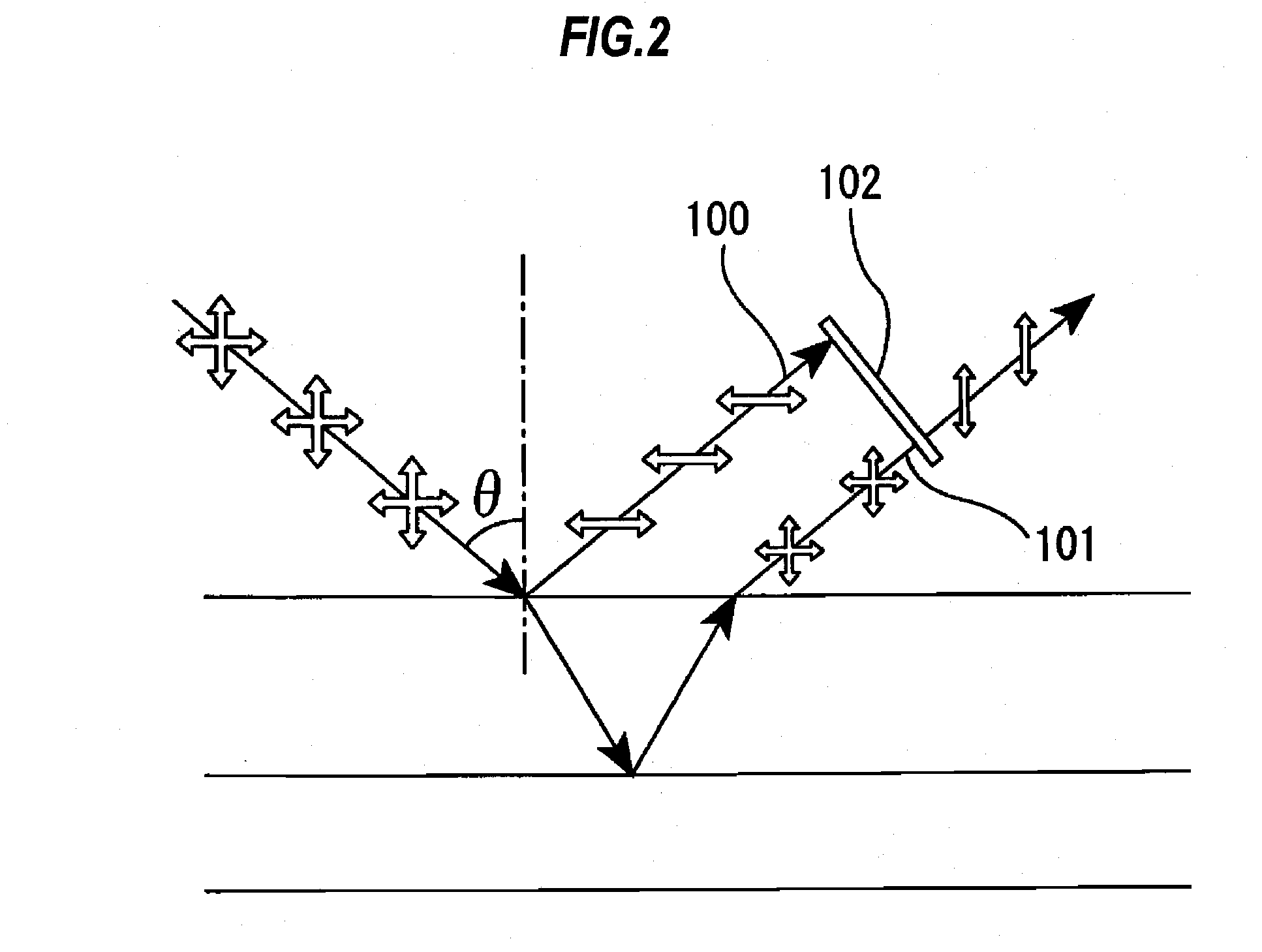
[0069]The principle of the present invention will now be described with reference to FIG. 2. When a light is incident on an interface between two substances having different indexes of refraction, p-polarized light is not reflected from the interface at a particular angle of incidence. This angle of incidence is called Brewster's angle, which is given by a known formula using the indexes of refraction of the two substances. FIG. 3 is a graph illustrating a reflectance of p-polarized light and a reflectance of s-polarized light that vary depending on the angle of incidence. As shown in FIG. 3, Brewster's angle given by indexes of refraction of air and SiO2 is 55.4 degrees, and Brewster's angle given by indexes of refraction of air and SiN is 63.4 degrees.

[0070]In FIG. 2, when the light is incident on the interface at an angle near the Brewster's angle θ, the reflected light is mainly com...


PUM


Abstract

A polishing end point detection method is to detect a polishing end point of a workpiece having a multilayer structure. The method is performed by emitting a first light and a second light to a surface of the workpiece at a first angle of incidence and a second angle of incidence, respectively, receiving the first light and the second light reflected from the surface through a polarizing filter, performing a first analyzing process of analyzing a brightness and a saturation of the surface from the first light received, performing a second analyzing process of analyzing a brightness and a saturation of the surface from the second light received, and determining removal of the upper layer based on changes in the brightness and the saturation of the surface.

Description

BACKGROUND OF THE INVENTION[0001]1. Field of the Invention[0002]The present invention relates to a polishing end point detection method, a polishing end point detection apparatus, and a polishing apparatus, and more particularly to a polishing end point detection method and a polishing end point detection apparatus for detecting an end point of polishing of a multilayer structure.[0003]2. Description of the Related Art[0004]An integrated circuit, which is a semiconductor device, is fabricated through several processes. STI (Shallow Trench Isolation) is one of such fabrication processes, and is important in realizing a finer integrated circuit. STI is a technique of electrically isolating elements, such as transistors, formed on a wafer (typically a silicon wafer) using an insulating film.[0005]FIG. 1 is a cross-sectional view illustrating a process of STI. More specifically, FIG. 1 shows a structure in which a SiO2 film 2 as an insulating film is embedded in grooves (or trenches) fo...

Claims


Application Information

Patent Timeline
Patent Type & Authority Applications(United States)
IPC IPC(8): G01J4/00
CPCB24B37/013G01N2021/215G01N21/211B24B49/12
Inventor KIMBA, TOSHIFUMI
Owner EBARA CORP
Why Eureka
Try Eureka