THz Wave Generation Device

a generation device and thz technology, applied in the direction of optics, instruments, active medium materials, etc., can solve the problems of increasing the size of the optical amplifier to gain the higher power, increasing the cost of the optical amplifier, etc., to achieve stable wavelength, high amplification characteristic, and low cost.

Inactive Publication Date: 2009-06-18
SUMITOMO OSAKA CEMENT CO LTD
View PDF8 Cites 13 Cited by
  • Summary
  • Abstract
  • Description
  • Claims
  • Application Information

AI Technical Summary

Benefits of technology

[0035]According to the first aspect of the invention, in a THz wave generator for generating a THz wave from a THz wave generating element by inputting a plurality of laser beams having different wavelengths to the THz wave generating element, at least one laser beam among the plurality of laser beams is a pulse beam, after amplifying the pulse beam by an optical amplifier, the pulse beam is inputted to the THz wave generating element, accordingly, the optical amplifier for the pulse beam which has high amplification characteristic and is inexpensive and compact in comparison with the optical amplifier amplifying constant beams, can be used, as a result, the very high-power THz wave generator restricting increase in manufacturing cost and large size of the entire apparatus can be provided.
[0036]According to the second aspect of the invention, since the plurality of laser beams having different wavelengths are generated by inputting single wavelength beam from single mode laser light source to a multi wavelength generator and by inputting light waves having a plurality of wavelengths generated from the multi wavelength generator to wavelength selecting means, the plurality of laser beams having different wavelengths with small change of wavelengths can be provided. In addition, since the plurality of wavelength beam are generated from single laser beam, it is easy to maintain the wavelength difference (frequency difference) among the wavelengths in a predetermined value, since frequency of the THz wave which is generated by the frequency difference of the laser beams inputted to the THz wave generating element is determined, the THz wave with a very stable waveleng

Problems solved by technology

However, when the power of the laser beam is amplified up to 10 mW to several W by the optical amplifier, the power of the THz wave is

Method used


Image

  • THz Wave Generation Device
  • THz Wave Generation Device
  • THz Wave Generation Device

Examples


first embodiment

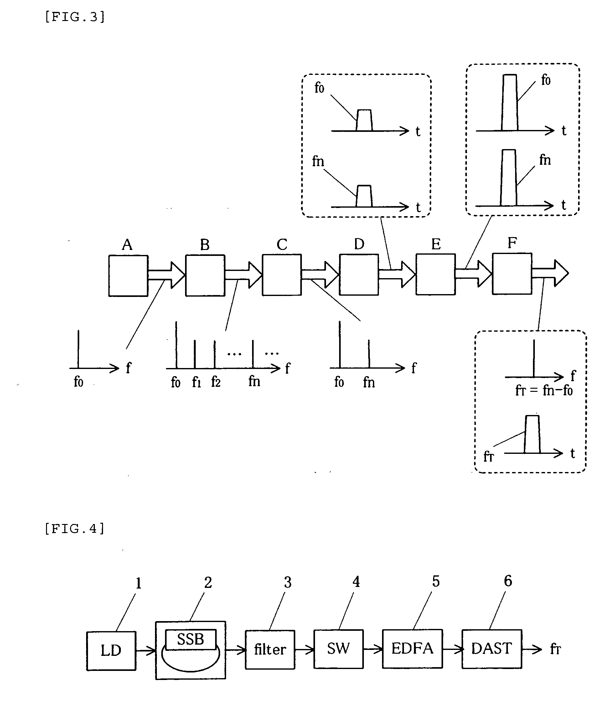
[0117]FIG. 4 shows the first embodiment according to the THz wave generator of the invention.

[0118]In the first embodiment, an outgoing beam from a laser light source (LD) 1 is transformed into a multi wavelength laser beam by a light circulating unit 2 including an SSB optical modulator and the light waves with two particular wavelengths are selected by a filter 3. The two selected light waves are formed into the pulse beams with a same phase by an optical switch (SW) 4 and are injected to an erbium-doped fiber-amplifier (EDFA) 5.

[0119]The two pulse beams having the different wavelengths amplified by the EDFA generate the THz wave (fτ) by being inputted to DAST crystals (DAST) 6. Since the light wave inputted to the DAST needs to control a polarization plane, a polarizer is disposed between the EDFA 5 and the DAST 6.

second embodiment

[0120]FIG. 5 shows the second embodiment according to the THz wave generator of the invention.

[0121]The outgoing light wave from the LD 1 is divided into two beams and the one light wave (frequency f0) is directly inputted to the DAST 6. The other light wave same as the first embodiment is transformed into the light wave having the frequency f0 and the different wavelengths (frequency fn) by the light circulating unit 2 including the SSB optical modulator and the filter 3 and is formed into the pulse beam by SW 4 and then is amplified by EDFA 5.

[0122]The light wave (frequency f0) inputted directly from the LD 1 and the pulse beam (frequency fn) amplified by the EDFA 5 are inputted to the DAST 6 after adjusting the polarization plane with being coupled.

[0123]The light wave with the frequency f0 is the constant beam and the light wave with the frequency fn is pulse beam but it is possible to generate the THz wave on the pulse in the DAST 6.

[0124]In addition, the light wave with freque...

third embodiment

[0125]FIG. 6 shows the third embodiment according to the THz wave generator of the invention.

[0126]The third embodiment is equal to the second embodiment until two beams of the frequency f0 and fn are generated but since the two light waves are amplified, the two light waves are coupled and formed into the pulse beam by the SW 4 and amplified by the EDFA 5. The SW or the EDFA can be applied in the the light waves but it is preferable that the two are shared so as to reduce the number of the parts.

[0127]As the third embodiment, so as to form the two light waves having the different wavelengths into the pulse beam by the same pulse generator, it is needed to apply a method that a switching characteristic do not depend on the length of the light wave. For example, the marketed Mach-Zehnder interference high-speed optical modulator for the optical digital communication as the modulator with high-speed (generating the pulse-of below the 10 ns) can be used. From a point of view of high-ex...


PUM


Abstract

[Task] To provide the THz wave generator restricting increase in manufacturing cost or large size of the entirety of the apparatus and generating efficiently the several-W THz wave.
[Means for Resolution] In a THz wave generator for generating a THz wave from a THz wave generating element by inputting a plurality of laser beams having different wavelengths to the THz wave generating element, at least one laser beam among the plurality of laser beams is formed into a pulse beam by the pulse generator and the pulse beam is amplified by an optical amplifier E and then the pulse beam is inputted to the THz wave generating element F. Preferably, the plurality of laser beams having different wavelengths are generated by inputting single wavelength beam to a multi wavelength generator from single mode laser light source and by inputting light waves having a plurality of wavelengths generated from the multi wavelength generator to wavelength selecting means.

Description

TECHNICAL FIELD [0001]The present invention relates to a THz (tera-hertz) wave generator, and more particularly, to a THz wave generator which generates a THz wave by inputting a laser beam from a light source including a laser light source to a THz wave generating element.BACKGROUND ART [0002]A THz (tera-hertz) wave is an infrared ray having a wavelength of 30 μm to 300 μm and an ultra-high frequency electromagnetic wave having a frequency 1 THz or more.[0003]The THz wave is expected to be widely used in the fields of basic science, engineering, and medicine-biology. For example, in the field of basic science, the THz wave is used in a structure elucidation of physical and chemical materials using a spectroscopy, a discovery of interstellar materials by radio wave frequency and infrared astronomy and spectroscopy science, and the like. In the field of engineering, the THz wave is used in a THz wave ultra-high-speed communication (cosmic space communication and the like), a geo-envi...

Claims


Application Information

Patent Timeline
IPC IPC(8): G02F1/355H01S3/11H01S3/16
CPCG02F1/3534G02F2202/02G02F2203/13H01S3/30H01S3/0078H01S3/06754H01S3/1608H01S1/02
Inventor ICHIKAWA, JUNICHIRO
Owner SUMITOMO OSAKA CEMENT CO LTD
Why Eureka
Try Eureka