
MIMO antenna receiving apparatus and receiving method

Inactive Publication Date: 2009-06-18
ELECTRONICS & TELECOMM RES INST
View PDF10 Cites 10 Cited by
  • Summary
  • Abstract
  • Description
  • Claims
  • Application Information

AI Technical Summary

Benefits of technology

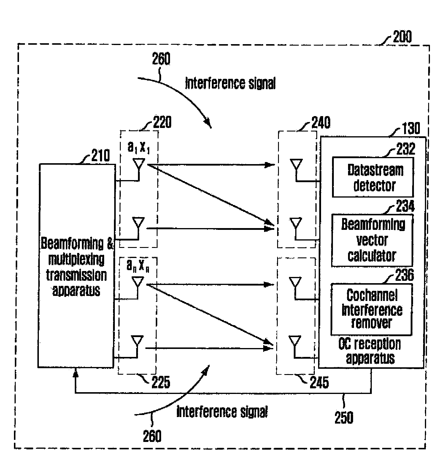
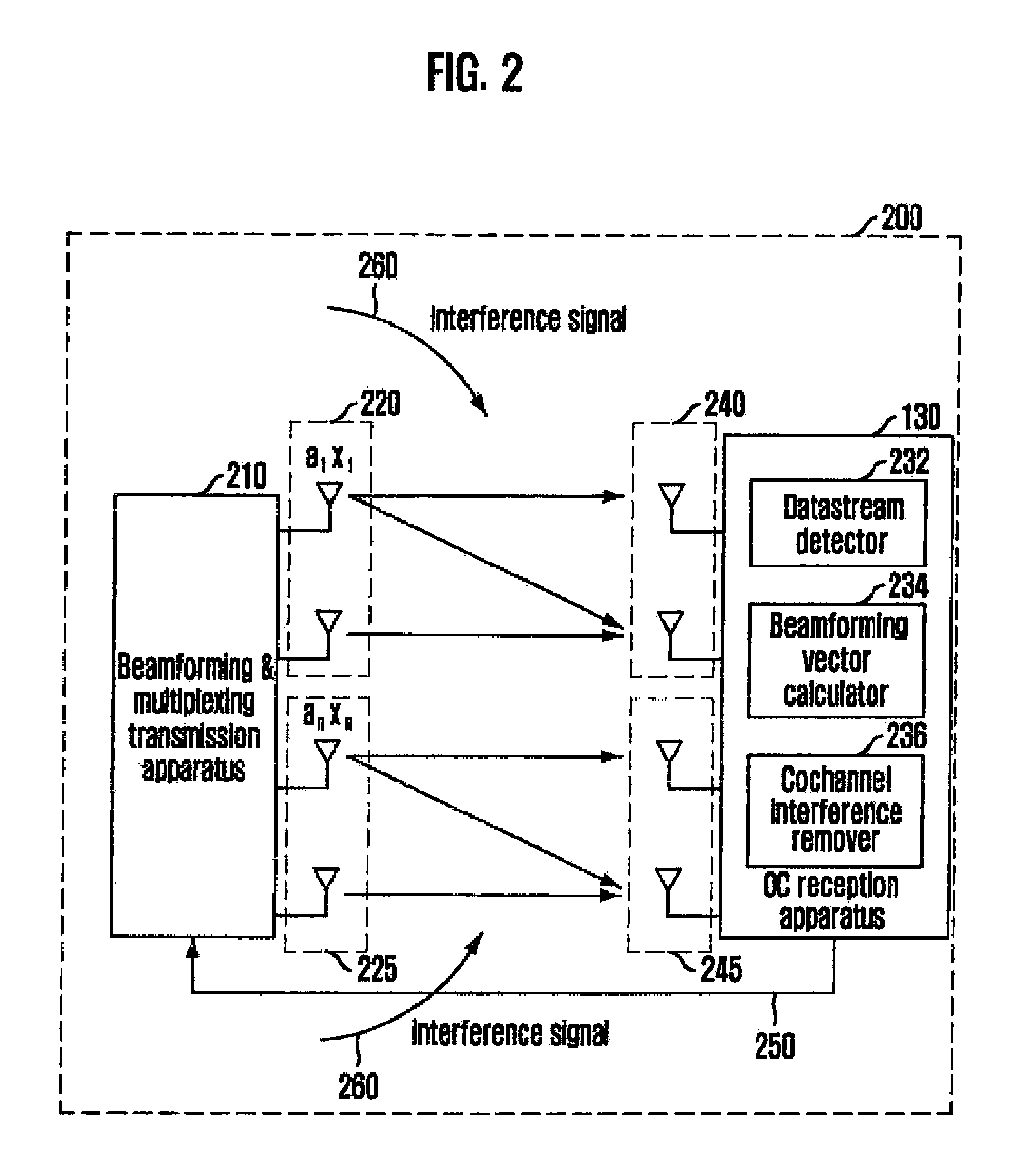
[0019]An embodiment of the present invention is directed to providing a reception apparatus and method of a Multiple Input Multiple Output (MIMO) antenna system that can secure high data transmission rate while minimizing influence of cochannel interference based on QR decomposition, beamforming, and optimal combining technology to thereby produce a maximal output signal-to-interference-plus-noise ratio (SINR).

Problems solved by technology

However, when an antenna transmits and receives a plurality of different data streams based on beamforming and optimum combining technology, interference may be added to the combination of the different data streams, which leads to performance deterioration.
The conventional MIMO antenna systems may increase transmission liability but it does not reach a transmission rates required for high-speed wireless communication.
In short, the conventional MIMO antenna systems have a problem in that they cannot acquire multiplexing gain.
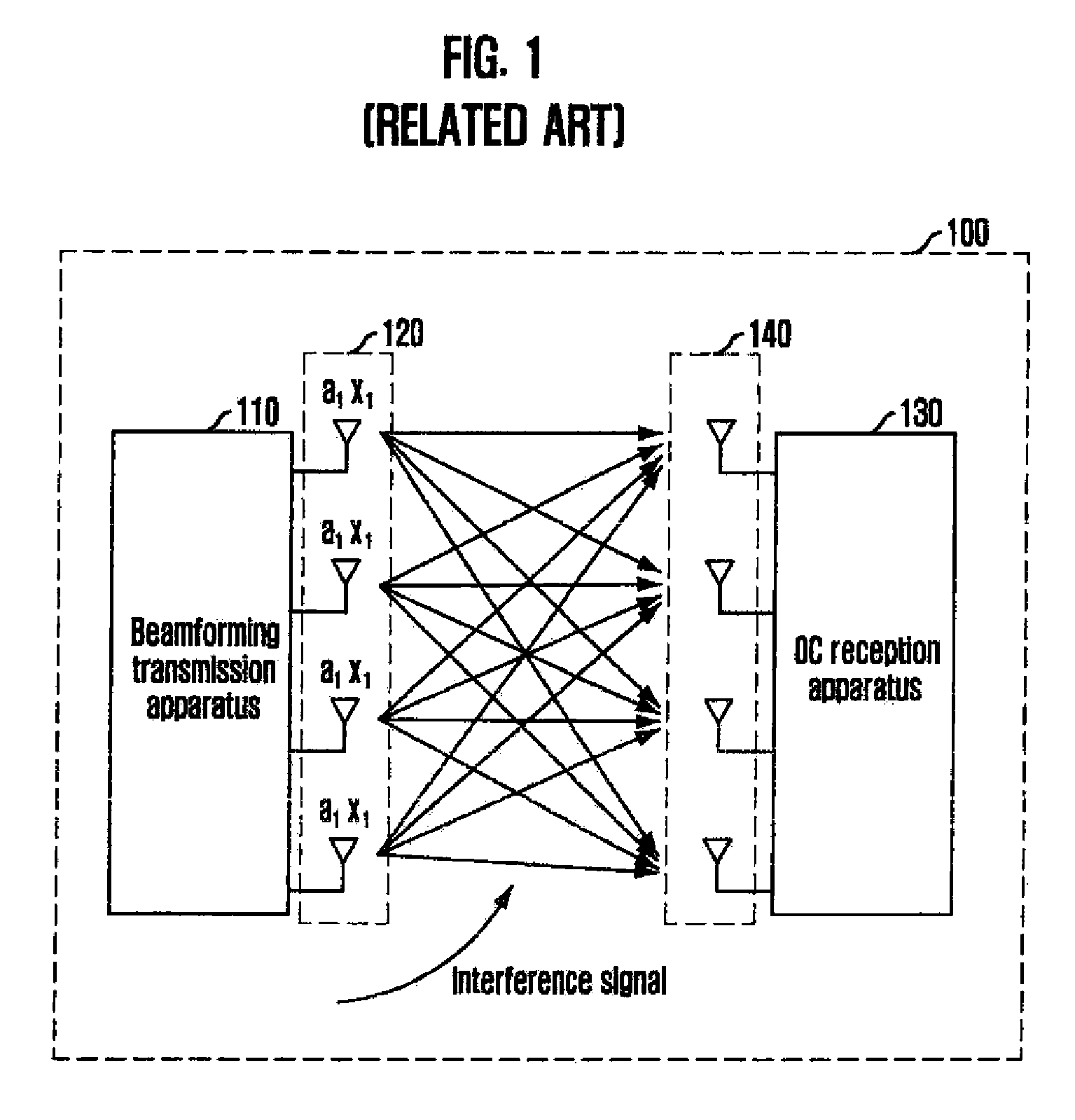
However, when a plurality of different data steams (a1x1, a2x2, a3x3 and a4x4) are transmitted through each of the transmission antennas, both cochannel interference and interference between bit streams occur at the same time.
However, when a plurality of different bit streams are transmitted simultaneously, it cannot performing the combining and thus it cannot acquire multiplexing gain.
However, the conventional technology has a shortcoming that cochannel interference cannot be removed.
In other words, the conventional technology cannot acquire diversity gain.
However, the singular value decomposition technology and the V-BLAST technology described before cannot use the combining technology because they transmit independent data streams from all transmission antennas.
After all, all the antennas of the reception apparatus are used to remove the interference between the independent data streams, the convention technologies cannot prevent performance deterioration cause by cochannel interference.

Method used


Image

  • MIMO antenna receiving apparatus and receiving method
  • MIMO antenna receiving apparatus and receiving method
  • MIMO antenna receiving apparatus and receiving method

Examples


Embodiment Construction

[0032]The advantages, features and aspects of the invention will become apparent from the following description of the embodiments with reference to the accompanying drawings, which is set forth hereinafter. Also, when it is considered that detailed description on a related art may obscure a point of the present invention, the description will not be provided herein. Hereinafter, specific embodiments of the present invention will be described with reference to the accompanying drawings.

[0033]The present invention provides a reception apparatus and method of a Multiple Input Multiple Output. (MIMO) antenna system that receives a plurality of different data streams transmitted from a transmission apparatus with multiple antennas through multiple reception antennas The words “a plurality of different data streams” refer to data streams independent from each other, and they are simultaneously transmitted through multiple antennas set up in the transmission apparatus. Each of the transmi...


PUM


Abstract

Provided is a reception apparatus and method of a Multiple Input Multiple Output (MIMO) system that receives a plurality of different data streams in a multiple cell environment. The reception apparatus for receiving a plurality of different data streams in a multiple input multiple output (MIMO) antenna system includes a data stream detector for detecting each data stream by removing interference between the different data streams while maintaining channel information; and a cochannel interference (CCI) remover for removing cochannel interference from each data stream detected in the data stream detector. The present invention can remove cochannel interference and increase channel capacity to thereby acquire both diversity gain and multiplexing gain.

Description

CROSS-REFERENCE(S) TO RELATED APPLICATIONS[0001]The present invention claims priority of Korean Patent Application No. 10-2007-0129972, filed on Dec. 13, 2007, which is incorporated herein by reference.BACKGROUND OF THE INVENTION[0002]1. Field of the Invention[0003]The present invention relates to a reception apparatus and method of a Multiple Input Multiple Output (MIMO) system that receives a plurality of different data streams in a multiple cell environment.[0004]This work was supported by the IT R&D program of MIC / IITA [2006-S-002-02, “IMT-Advanced Radio Transmission Technology with Low Mobility”].[0005]2. Description of Related Art[0006]Optimum Combining (OC) technology is used in designing a wireless communication system in a multi-cell environment to remove cochannel interference and thereby prevent deterioration in performance caused by the cochannel interference (CCI). As the field of wireless communication services extends from conventional low-speed voice communication to...

Claims


Application Information

Patent Timeline
IPC IPC(8): H04L1/02H04B7/02H04B1/10
CPCH04L1/0631H04B7/0417H04B7/0617H04B7/0619H04L1/0048H04L1/02
Inventor CHEONG, MINHOLEE, YU-ROOH, JONG -EELEE, SOK-KYU
Owner ELECTRONICS & TELECOMM RES INST
Learn More