Thermal power plant incorporating subterranean cooling of condenser coolant

a technology of condenser and cooling tower, which is applied in the direction of machines/engines, light and heating equipment, transportation and packaging, etc., can solve the problems of dry cooling process less efficient than evaporative cooling, evaporative cooling towers lose water to evaporation, etc., to achieve maximum heat dissipation

Inactive Publication Date: 2009-06-25
AREVA SOLAR
View PDF10 Cites 32 Cited by
  • Summary
  • Abstract
  • Description
  • Claims
  • Application Information

AI Technical Summary

Benefits of technology

[0016]With the above described shielding arrangement the ground in which the heat exchanger is buried will be able to absorb heat from the heat exchanger in an amount at least equal to the heating effect of solar radiation that would otherwise impinge on the relevant area, without “ex...

Problems solved by technology

However, evaporative (wet) cooling towers lose water to evaporation and require sources of clean top-up water for sustained operation.
Also, their open construction permits pollution of the coolant water by contaminants from the atmosphere and, whilst controlled draining and chemical treatments are in practice employed to minimise the concentration of contaminants, evaporative cooling remains unsuitable for use with direct contact condensers.
These towers employ forced air cooli...

Method used


Image

  • Thermal power plant incorporating subterranean cooling of condenser coolant
  • Thermal power plant incorporating subterranean cooling of condenser coolant
  • Thermal power plant incorporating subterranean cooling of condenser coolant

Examples


Embodiment Construction

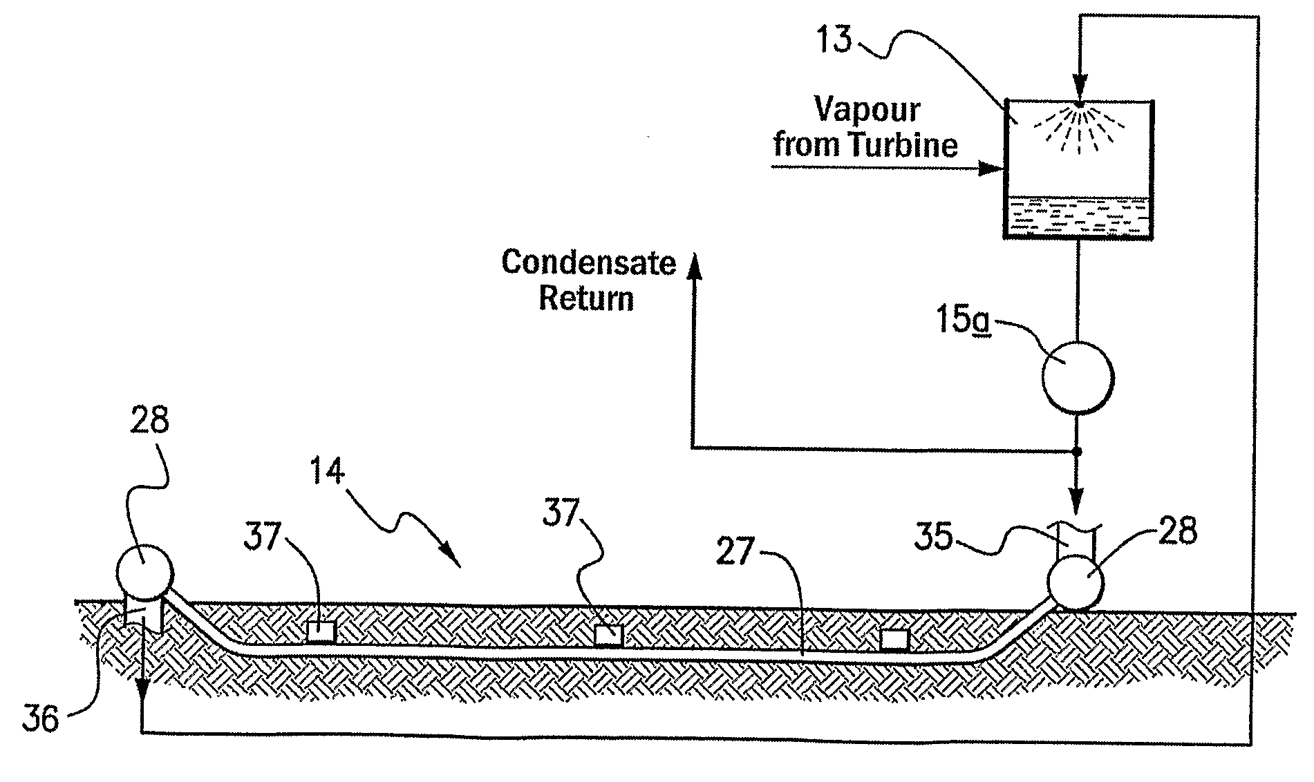
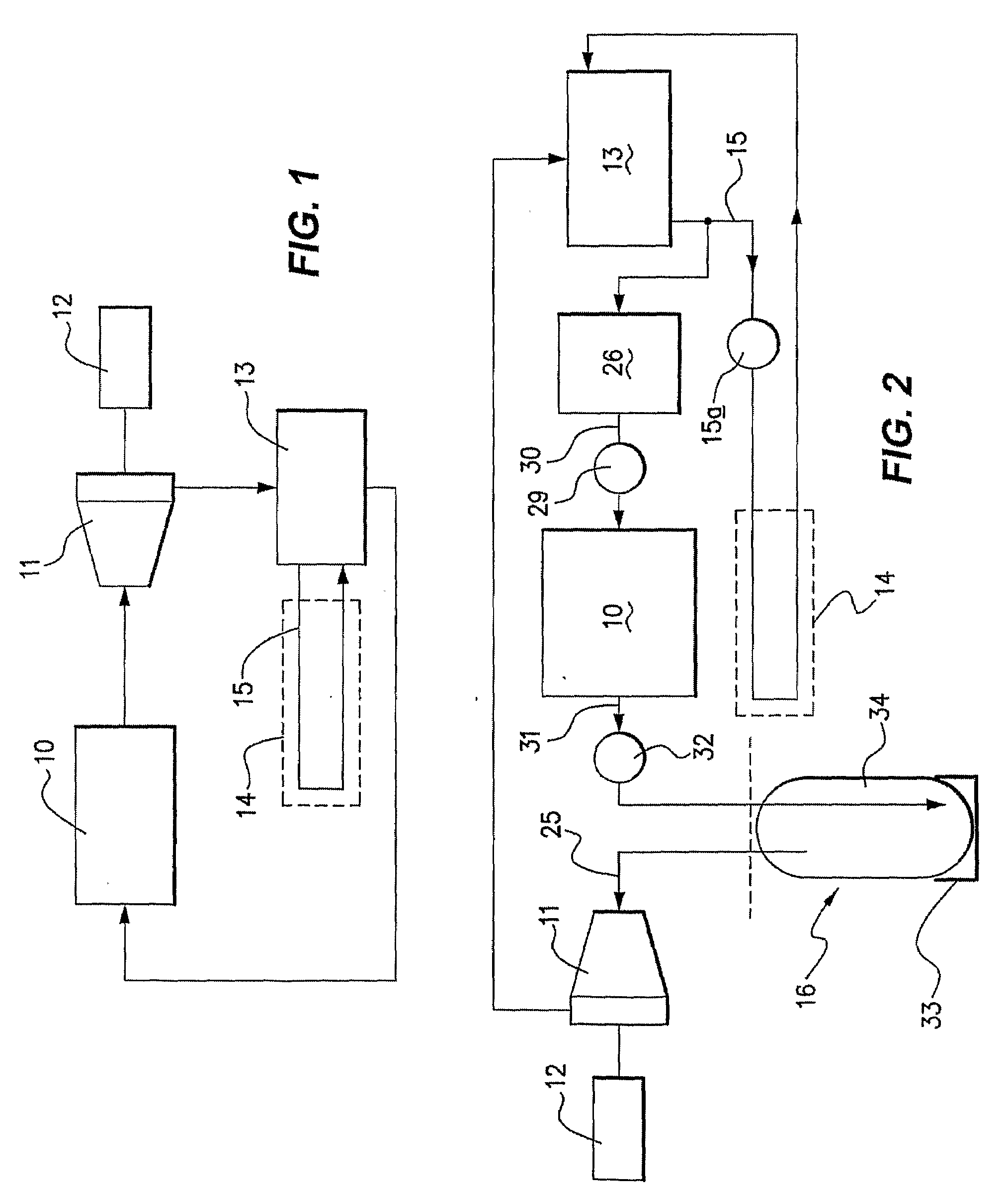
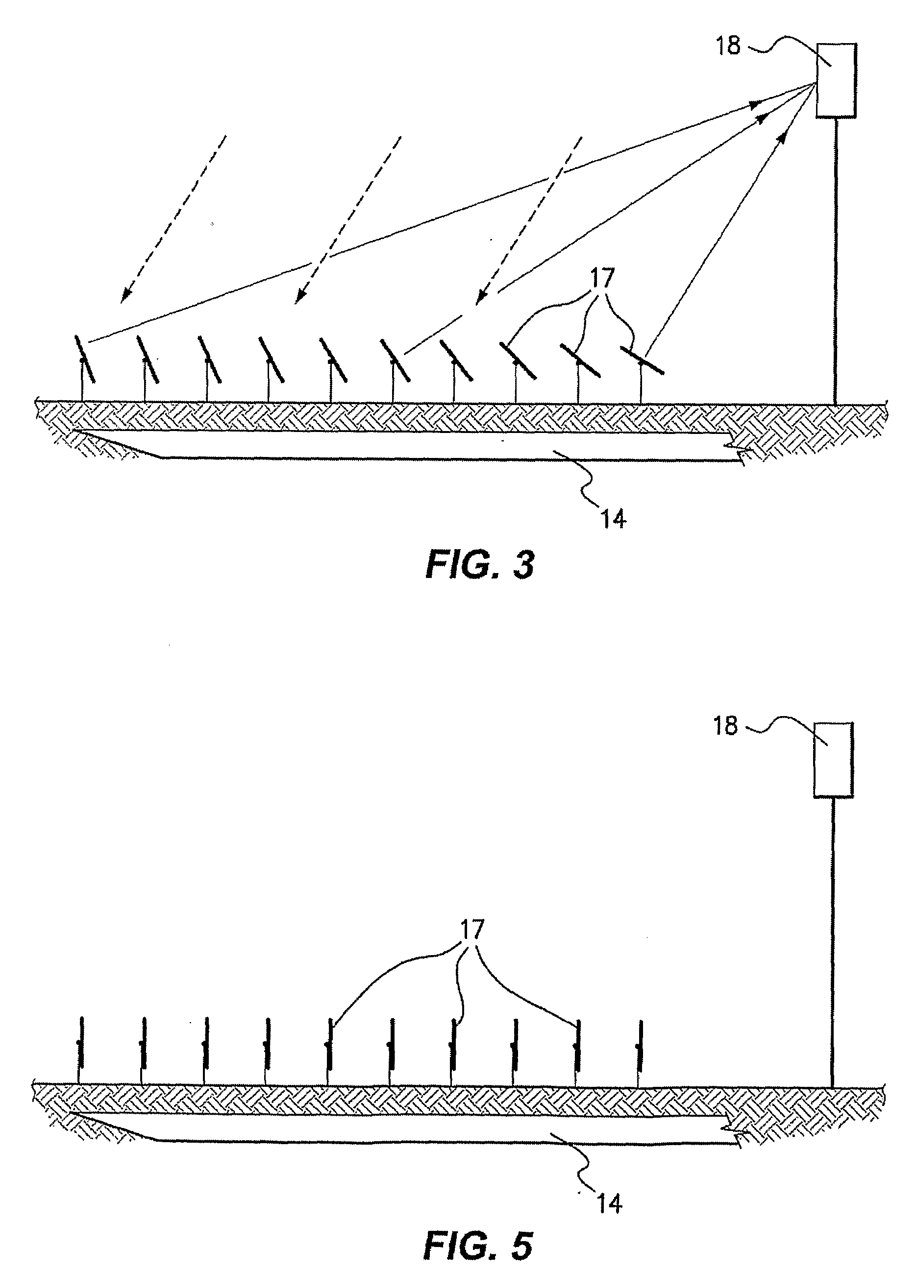
[0029]As illustrated in FIG. 1, the thermal power plant comprises a heating system 10 in which heat is transferred to a working fluid. The heating system utilizes solar energy, as hereinafter described more fully with reference to FIGS. 3 to 5.

[0030]The working fluid may comprise a hydrocarbon or such other fluid as is suitable for expanding through a turbine, but the working fluid preferably comprises water or, in its vapour / gaseous phase, steam. The working fluid when heated is delivered to a turbine 11 which is employed to drive an electrical generator 12 and, having expanded through the turbine, the working fluid is then passed to a condenser 13 where residual vapour is condensed to a liquid phase. From the condenser 13 the working fluid is returned to the heating system 10.

[0031]Both the turbine 11 and the condenser 13 are selected to meet design parameters as determined, for example, by required output power, operating temperature and operating pressure. The condenser 13 may c...


PUM


Abstract

A thermal power plant is disclosed that comprises a heating system (10) that utilizes solar radiation for heating a working fluid, a turbine (11) to which, in operation, the working fluid is delivered, a condenser (13) located downstream from the turbine and arranged for condensing vapour exhausted from the turbine, and a cooling system (14) associated with the condenser. The heating system comprises a field of reflectors (17) that, during diurnal periods, are arranged (for example by pivoting) to reflect incident solar radiation to a receiver (18) for heating the working fluid. The cooling system (14) is arranged in operation of the power plant to transport a coolant fluid to which heat is transferred during vapour condensing and it comprises a subterranean heat exchanger incorporating conduits (27) through which the coolant is recirculated when cycling through the condenser. In one embodiment of the power plant the cooling system/subterranean heat exchanger (14) is positioned within ground that is located at least in part below the field of reflectors (17). Also disclosed is a method of operating a thermal power plant.

Description

FIELD OF THE INVENTION[0001]This invention relates to a thermal power plant that utilizes solar radiation for heating a working fluid and which incorporates subterranean cooling of condenser coolant.BACKGROUND OF THE INVENTION[0002]A thermal power plant typically comprises a steam producing plant, a steam turbine to which the steam is fed, a condensing plant located downstream from the turbine and a cooling system associated with the condensing plant. Also included in the power plant are such ancillary components and systems as provide for fluid reticulation, fluid storage, water / steam separation and heat recuperation, and the turbine is employed to drive an associated electrical generator. The working fluid (in its liquid phase) may comprise water alone or a water-mixture containing an additive such as ammonia. An alternative, less typical, thermal power plant employs a so-called organic Rankine cycle in which a hydrocarbon working fluid (such as pentane or a pentane-hexane mixture...

Claims


Application Information

Patent Timeline
IPC IPC(8): F01D15/10F24J2/32F24J2/42F03G6/06F24S10/95F24S90/00
CPCF01D15/005F02C1/05F03G6/065F24J2/07Y02E10/46F24J2002/1076F28B9/06Y02E10/41F24J2/16F24S20/20F24S2023/87F24S23/77Y02E10/40
Inventor MIERISCH, ROBERT CHARLES
Owner AREVA SOLAR
Why Eureka
Try Eureka