Systems for and methods of controlling operation of a ups

a technology of dc bus voltage and ups, applied in the field of uninterruptible power supplies, can solve the problems of deviation from nominal voltage, poor transient response, and relatively slow response time of the voltage control loop, and achieve the effect of reducing voltage “excursions”

Active Publication Date: 2009-06-25
AMERICA POWER CONVERSION CORP
View PDF4 Cites 44 Cited by
  • Summary
  • Abstract
  • Description
  • Claims
  • Application Information

AI Technical Summary

Benefits of technology

[0009]At least one aspect of the invention provides an effective approach for dynamic control of voltage on a DC bus used in power conversion circuitry. According to one embodiment, data concerning changes in the load supplied by the power conversion circuitry is used to control a transient response of the DC bus voltage. In a further embodiment, a difference between instantaneous load power measured during a first cycle and instantaneous power measured during a second cycle is accumulated and the voltage of the DC bus is controlled based on the accumulated difference. According to one embodiment, the preceding approach is employed in a single phase system. In a further embodiment, the preceding approach is employed in controlling a transient response of a DC bus vo

Problems solved by technology

Generally, power conversion circuitry designed for reduced harmonics, however, must employ a voltage control loop that has a relatively slow response time.
The slow response time results in a poor transient response including wider deviations from nominal voltages, for example, greater overshoot and undershoot of a DC bus voltage.
The result of the design tradeoff included in this approach is that the DC bus voltage has a relatively poor transient response.
The poor transient approach can result in large overvoltages and undervoltages on the DC bus as the DC bus voltage varies, for example, in response to changes in the lo

Method used


Image

  • Systems for and methods of controlling operation of a ups
  • Systems for and methods of controlling operation of a ups
  • Systems for and methods of controlling operation of a ups

Examples


Embodiment Construction

[0018]This invention is not limited in its application to the details of construction and the arrangement of components set forth in the following description or illustrated in the drawings. The invention is capable of other embodiments and of being practiced or of being carried out in various ways. Also, the phraseology and terminology used herein is for the purpose of description and should not be regarded as limiting. The use of “including,”“comprising,” or “having,”“containing”, “involving”, and variations thereof herein, is meant to encompass the items listed thereafter and equivalents thereof as well as additional items.

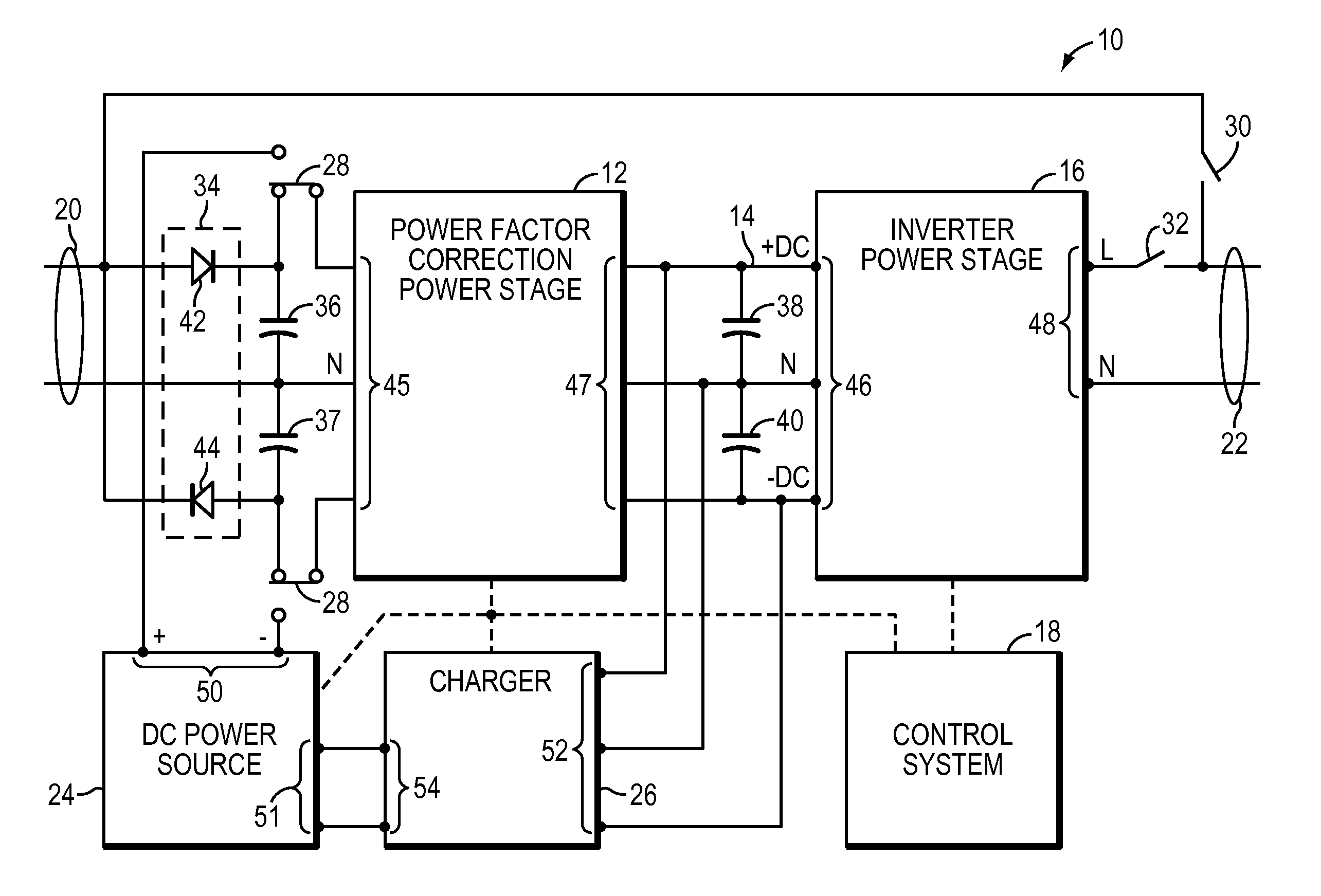
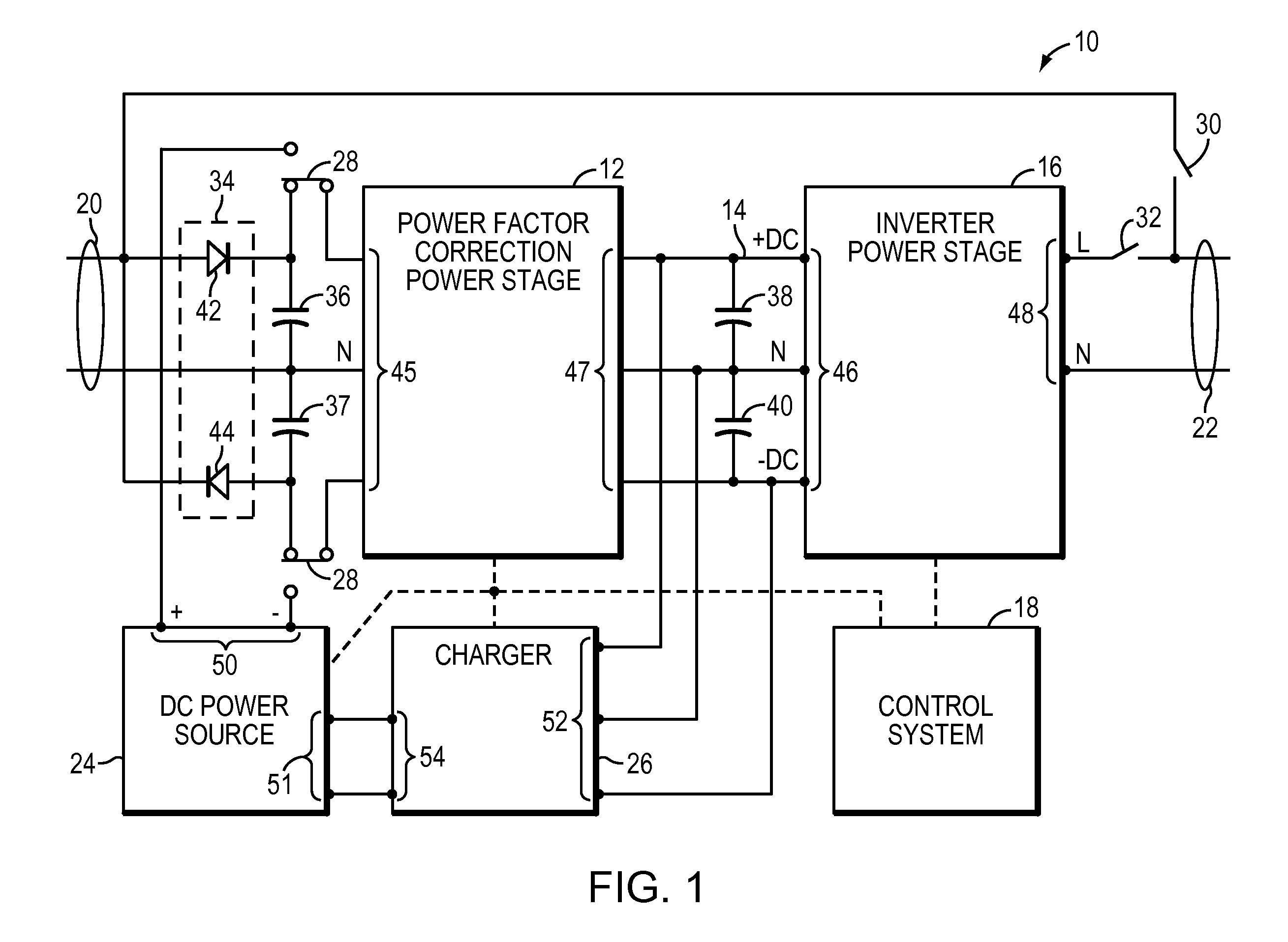
[0019]FIG. 1 illustrates a block diagram of an embodiment in which a control system is employed to regulate a voltage on a DC bus of power conversion equipment through various changes in the loading of the equipment, e.g., through load transients that occur at the output. In accordance with one embodiment, a UPS 10 includes a power factor correction stage 12, a...


PUM


Abstract

A UPS includes an AC output, power factor control circuitry; and a DC bus coupled to the power factor control circuitry where the power factor control circuitry is configured to determine a difference in instantaneous power supplied to the AC output and to adjust a voltage of the DC bus based, at least partly, on the difference. In one embodiment, the UPS includes a single phase AC input. In another embodiment, the power factor control circuitry is configured to determine a cumulative difference in instantaneous power supplied to the AC output.

Description

BACKGROUND OF INVENTION[0001]1. Field of Invention[0002]Embodiments of the invention relate generally to uninterruptible power supplies (“UPS”). More specifically, at least one embodiment relates to a system and method for controlling a DC bus voltage of a UPS.[0003]2. Discussion of Related Art[0004]Because electrical systems are dynamic in nature, control systems employed with power conversion circuitry are generally responsive to changes in the electrical systems. Different approaches may be employed to address various types of changes, for example, transient or steady state changes, changes in voltage and / or current, changes in the connected load, combinations of the preceding examples, etc.[0005]Today, power factor correction of power conversion circuitry (i.e., the phase relation between the current and the voltage used by the power conversion circuitry) is a significant design consideration. In practice, power factor can be improved by reducing harmonics generated by the power...

Claims


Application Information

Patent Timeline
IPC IPC(8): H02J9/00
CPCH02J9/062H02M1/4208H02M2001/0019Y02B70/126H02M2001/007H02M1/007Y02B70/10Y02P80/10
Inventor WU, JIASIMONELLI, JAMESBUSH, MATTHEW F.
Owner AMERICA POWER CONVERSION CORP
Why Eureka
Try Eureka