Method and apparatus for providing high speed, low EMI switching circuits

Inactive Publication Date: 2009-06-25
APPLE INC
View PDF2 Cites 4 Cited by
  • Summary
  • Abstract
  • Description
  • Claims
  • Application Information

AI Technical Summary

Benefits of technology

[0005]In accordance with embodiments of the invention, methods and apparatus are provided for generating supply voltages for display driver circuits at very high efficiencies and with low quantities of radiated energy (i.e., low noise). In particular, the methods and apparatus are provided to utilize switching regulator circuits that have been modified such that multiple circuit paths are created which carry electric current in opposite directions in order to cancel out the radiated noise of each path. In addition, additional terminal lines are provided which act to sink any electromagnetic interference (EMI) generated in the outermost paths that are actively coupled to the circuit (e.g., the paths in which current flows).
[0006]Embodiments of the present invention provide the capability to produce relatively large amounts of current, which can be used in driver circuits for relatively large displays such as the Apple iPhone display, without incurring the typical penalties associated with EMI or noise in such implementations. In conventional implementations of chip on glass (COG), an integrated circuit (IC) may be located on one side of the glass used in displays. The IC may include a transistor which operates as the switch in the switching regulator. The transistor may include multiple parallel leads connected to the source and multiple parallel leads connected to the drain. The leads may be connected to a piece of flex circuitry to complete the circuit via circuit elements formed of indium tin oxide (ITO). ITO is particularly useful in display applications because it is a transparent material, but it has a high resistance (it may be on the order of about 10 ohms or so), which can result in a voltage drop of about 500 millivolts.
[0010]Therefore, in accordance with the present invention, there is provided methods and apparatus for producing sufficient current to drive circuits for relatively large displays, such as the Apple iPhone, which do not generate the electromagnetic interference (EMI) typically associated with such circuits. In addition, the reduction in EMI can be increased through the use of terminal leads.

Problems solved by technology

ITO is particularly useful in display applications because it is a transparent material, but it has a high resistance (it may be on the order of about 10 ohms or so), which can result in a voltage drop of about 500 millivolts.

Method used


Image

  • Method and apparatus for providing high speed, low EMI switching circuits
  • Method and apparatus for providing high speed, low EMI switching circuits
  • Method and apparatus for providing high speed, low EMI switching circuits

Examples


Embodiment Construction

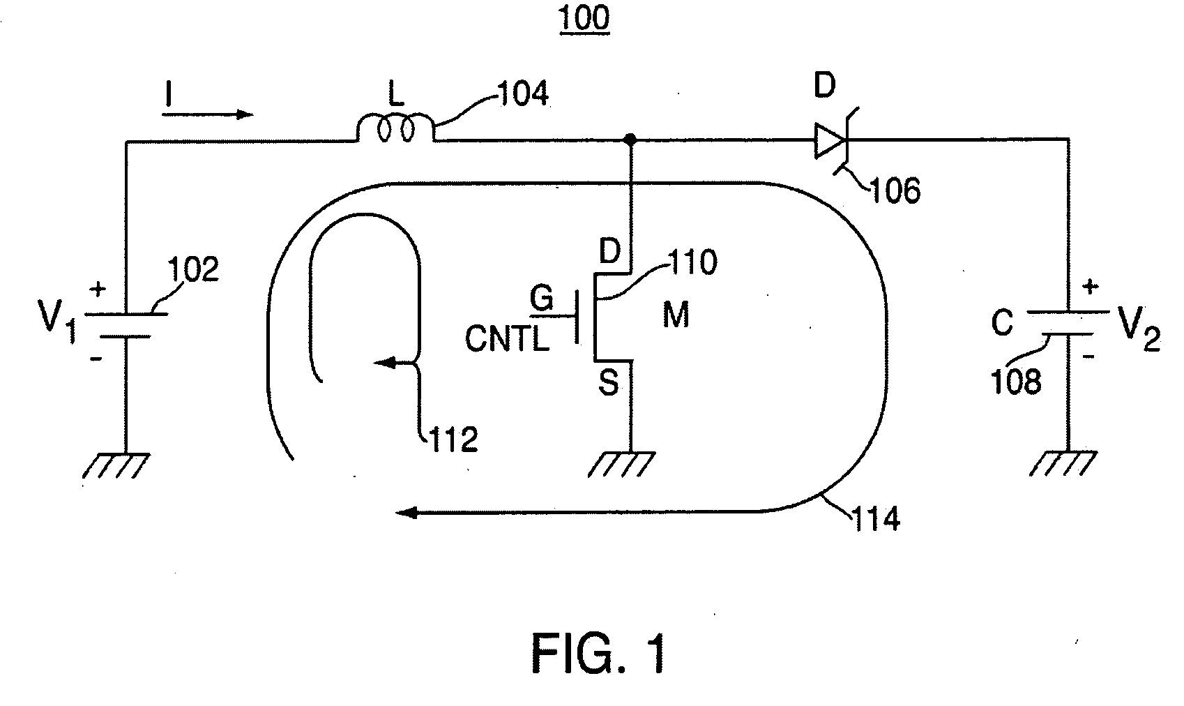
[0017]FIG. 1 shows a switching regulator circuit 100 that can be implemented in accordance with the principles of the present invention. Switching regulator 100 may include a voltage source 102 that produces a voltage V, an inductor 104 that stores a current I, a diode 106 that prevents energy from the output device from being drained by the switching regulator, and a transistor switch 110. Diode 106 is coupled to capacitor 108, which provides the output voltage to the display driver circuit (not shown). As shown, voltage source 102 is configured to be connected between ground and inductor 104. Inductor 104 may be coupled to both diode 106 and to the drain of transistor 110 to provide operation as described below. The source of transistor 110 is coupled to ground, while the gate of transistor 110 is coupled to a control line. This configuration is commonly known as a boost regulator.

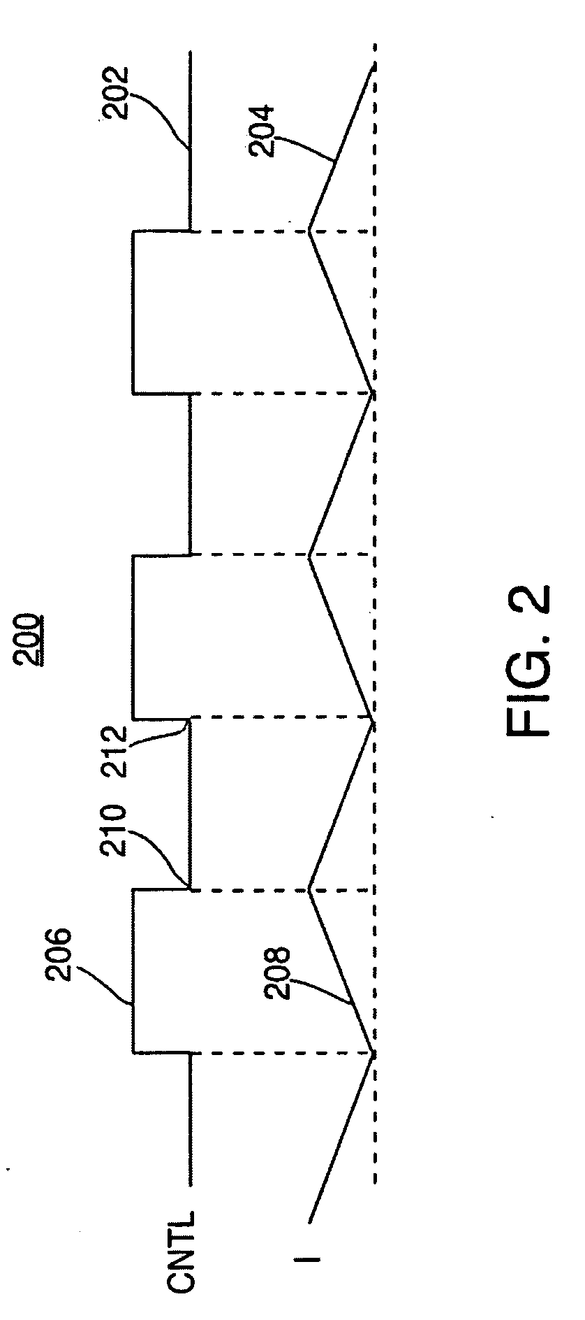
[0018]FIG. 2 shows a control timing diagram 200 that may be used to show the operation of switching r...


PUM

PropertyMeasurementUnit
Currentaaaaaaaaaa
Energyaaaaaaaaaa

Abstract

Methods and apparatus are provided for generating low EMI display driver power supply. The methods and apparatus include switching circuits that utilize two groups of parallel circuit traces, each of which is coupled to one end a switching device. The two groups of traces are configured to be interleaved with each other such that no two traces from either group are next to any other traces from the same group. When the switching device is activated, current flows through the circuit and charges an energy storage element. When the switching device is deactivated, the energy storage element discharges a portion of its energy to a second energy storage element and to the driver circuits. In another embodiment, and additional circuit trace is provided which is only connected on one end and is free floating on the other end to capture the majority of EMI remaining that was generated by the switching circuit.

Description

BACKGROUND OF THE INVENTION[0001]This relates to switching circuitry that may be used to drive display drivers, and particularly to providing switching circuitry that operates at switching high speeds while producing low EMI output.[0002]There are various well known techniques for generating supply voltages to display driver circuits. In one instance, for example, a charge pump circuit may be used to act as a high voltage power source for a display driver. In that instance, the charge pump could be configured to first charge a capacitor to a given voltage from a battery. Once charged, the capacitor may be placed in a series connection with the battery to effectively double the output voltage. For example, a 3 volt battery may be used to charge a capacitor, which could then be placed in series with the battery to provide a 6 volt output. Charge pumps often operate at relatively high energy efficiencies, but often don't provide as much current as other methods, such as a switching reg...

Claims


Application Information

Patent Timeline
IPC IPC(8): G09G3/00H02M3/155
CPCG09G3/20G09G2300/0426H02M1/44G09G2330/06G09G2330/02
Inventor LEE, YONGMAN
Owner APPLE INC
Why Eureka
Try Eureka