Method and apparatus for vibration-based automatic condition monitoring of a wind turbine

a technology of automatic condition monitoring and wind turbine, which is applied in the direction of vibration measurement in solids, liquid fuel engine components, non-positive displacement fluid engines, etc., can solve the problems of affecting reliability, requiring reliable frequency separation, and requiring detailed description of damage types

Active Publication Date: 2009-06-25
KK WIND SOLUTIONS VOJENS AS +1
View PDF7 Cites 24 Cited by
  • Summary
  • Abstract
  • Description
  • Claims
  • Application Information

AI Technical Summary

Benefits of technology

[0013]It is therefore an object of the present invention to provide a method and an apparatus for vibration-based automatic condition monitoring of a wind turbine which provides for reliable monitoring even under the particular conditions that are typical of wind turbines, while at the same time avoiding the limitations of the state of the art, as well as a wind turbine therefor.
[0016]By calculating and analysing the cepstrum of the frequency spectrum of the vibrations measured in the wind turbine, the configuration of the present invention generates highly precise and trendable values. In wind turbine environments, where vibrations due to irregular system behaviour are particularly difficult to detect, the application of the cepstrum proves to produce good monitoring results.
[0019]Thus, in spite of the monitoring of a wind turbine being much more complex than monitoring a bearing of a railway vehicle axle, the present invention proposes to invest the additional technical effort to calculate the cepstrum, and thus surprisingly provides for its reliable and precise wind turbine monitoring results.
[0028]In an embodiment, detecting the alarm condition based upon the amplitude of the cepstrum at the selected quefrency comprises the step of converting the amplitude to an indicator value. This indicator value facilitates further evaluation and can be based on a mean value of amplitudes, a rms value (root mean square value, or a peak value. Further, the indicator value can be calculated in the frequency domain, e.g. as the power of the harmonics which form the basis for the indicated quefrency, thus providing for more accurate results.

Problems solved by technology

However, detecting irregular behaviour of the system that has been present initially is not supported by this approach, and neither can the type of damage be characterized in detail.
However, this approach does not provide for reliable separation of frequencies that lie close to another, so that neighbouring effects significantly impair the reliability of results and thus the applicability of such systems.
Further, this approach suffers from a significant sensitivity to variations in background noise or randomly occurring signals in significant frequency bands.
Consequently, these systems may produce false alarms and thus provide only a limited specificity.
Moreover, such systems typically provide unsatisfactory results in environments where the amplitude level of a fault vibration signature is about equal to the amplitude level of the general background noise of the system.
While this approach provides for a fault detection at an even earlier stage than the approach discussed before, it generally suffers from the same limitations as that approach.
However, such an approach requires a significant extra effort in data processing due to its particular result form.
Also, the evaluation of amplitudes in this approach is difficult to reproduce.
Also in the frequency domain, the signal of any particular of the multitude of the monitored components appears rather mixed with signals of the other components, and also with general background noise.

Method used


Image

  • Method and apparatus for vibration-based automatic condition monitoring of a wind turbine
  • Method and apparatus for vibration-based automatic condition monitoring of a wind turbine
  • Method and apparatus for vibration-based automatic condition monitoring of a wind turbine

Examples


Embodiment Construction

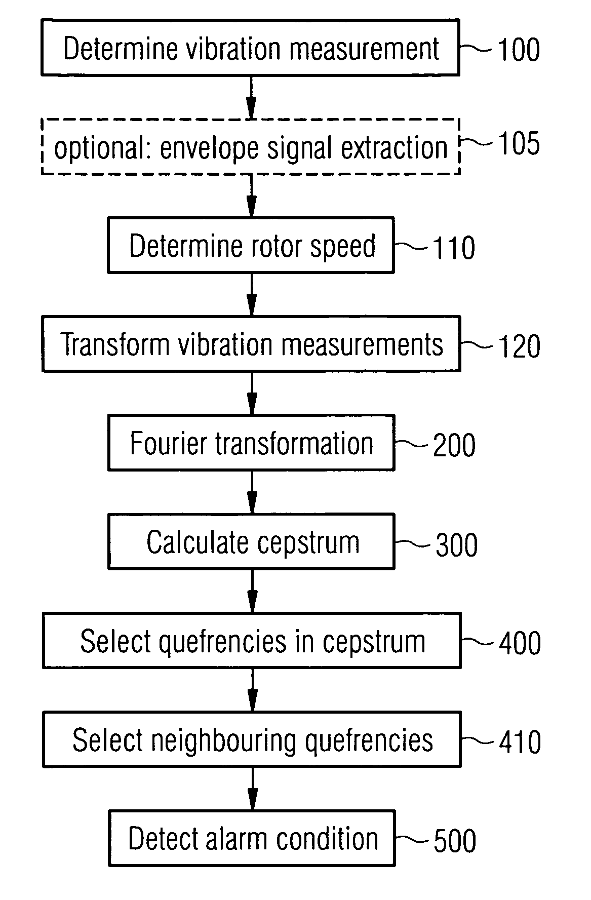
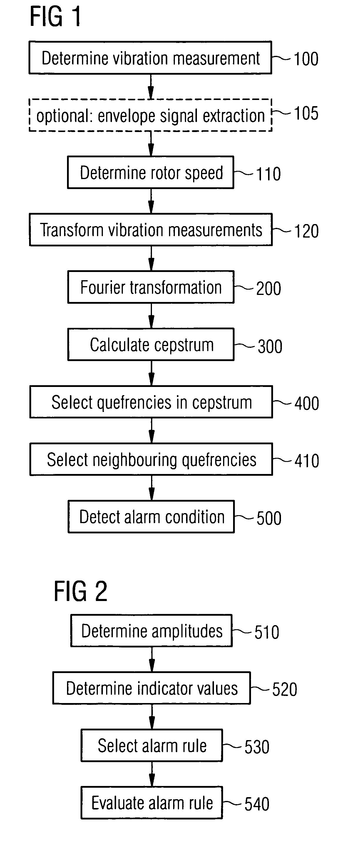
[0051]FIG. 1 shows a schematic overview of a first embodiment of the method of present invention. In step 100, a time series of vibration measurement values is obtained by receiving appropriate measurements from sensor systems located at or within the gearbox of a wind turbine.

[0052]While other embodiments may relate to wind turbines of constant rotor speed and thus may omit the following steps 110 and 120, in the present embodiment, the wind turbine is of variable rotor speed and its rotor speed is manipulated by a control system through braking or pitch control. In step 110, consequently, the rotor speed values corresponding to the vibration time series or, as a further possibility, to an envelope time series, is obtained, either by direct measurement with dedicated sensor systems or by receiving the measurement values from the control system. Then, in step 120, the time series of vibration measurements is transformed (scaled at the time domain) according to the variations in the ...


PUM


Abstract

Method and apparatus for vibration-based automatic condition monitoring of a wind turbine, comprising the steps of: determining a set of vibration measurement values of the wind turbine; calculating a frequency spectrum of the set of vibration measurement values; calculating a cepstrum of the frequency spectrum; selecting at least one quefrency in the cepstrum, and detecting an alarm condition based upon an amplitude of the cepstrum at the selected quefrency, and a wind turbine therefor.

Description

CROSS REFERENCE TO RELATED APPLICATIONS[0001]This application claims the benefits of European application No. 07024657.4 filed Dec. 19, 2007 and is incorporated by reference herein in its entirety.FIELD OF INVENTION[0002]The invention relates to a method and an apparatus for vibration-based automatic condition monitoring of a wind turbine, and a wind turbine therefor.BACKGROUND OF THE INVENTION[0003]For detecting particular conditions in mechanical systems, automatic condition monitoring systems are known which measure and analyse vibrations occurring in the mechanical system. In order to provide reliable monitoring with high safety and a minimum number of false alarms, which could occur due to difficulties in clearly distinguishing between fault frequencies background noise and / or random frequency peaks, it is desirable to optimize the accuracy of the employed automatic evaluation methods in such systems.[0004]Automatic vibration monitoring systems of the state of the art are typic...

Claims


Application Information

Patent Timeline
Patent Type & Authority Applications(United States)
IPC IPC(8): F04D15/00
CPCG01H1/06G05B23/024
Inventor CHRISTINSEN, AXEL JUHLGRAM-HANSEN, KLAUSMOELLER, TROELS KILDEMOES
Owner KK WIND SOLUTIONS VOJENS AS
Why Eureka
Try Eureka