Automatic analyzer and sample-processing system

a technology of automatic analyzer and sample processing, which is applied in the field of sample processing systems, can solve the problems of obstructing the processing of racks supplied from supply units, consuming time, and correspondingly consuming time, so as to reduce the processing time of the entire system and eliminate the functional dependence between any processing unit and a rack conveyance uni

Active Publication Date: 2009-06-25
HITACHI HIGH-TECH CORP
View PDF4 Cites 49 Cited by
  • Summary
  • Abstract
  • Description
  • Claims
  • Application Information

AI Technical Summary

Benefits of technology

[0015]A system according to the present invention includes a buffer unit that causes a plurality of racks to stand by for processing and has random accessibility to each rack, and the buffer unit is combined with each of multiple processing units to form a pair. The system is also constructed to load/unload each rack into/from the buffer unit. One unprocessed rack is loaded into the buffer unit and then upon completion of process steps up to automatic retesting, the rack is unloaded from the buffer unit. Functional dependence between any processing unit and a rack conveyance unit is thus eliminated.
[0016]In addition, if a rack transfer block that uses the buffer unit to transfer racks to and from a rack conveyance block is constructed to be able to access ...

Problems solved by technology

In addition to consuming time, such a conveying sequence will obstruct the processing of the racks supplied from the supply unit.
In a system configuration with a plurality of analytical units each different in processing rate, therefore, even when a rack is present that contains samples whose analytical results have already been output and which are to undergo retests, an unnecessary waiting time will occur since that...

Method used


Image

  • Automatic analyzer and sample-processing system
  • Automatic analyzer and sample-processing system
  • Automatic analyzer and sample-processing system

Examples


Embodiment Construction

[0038]An embodiment of the present invention will be described hereunder.

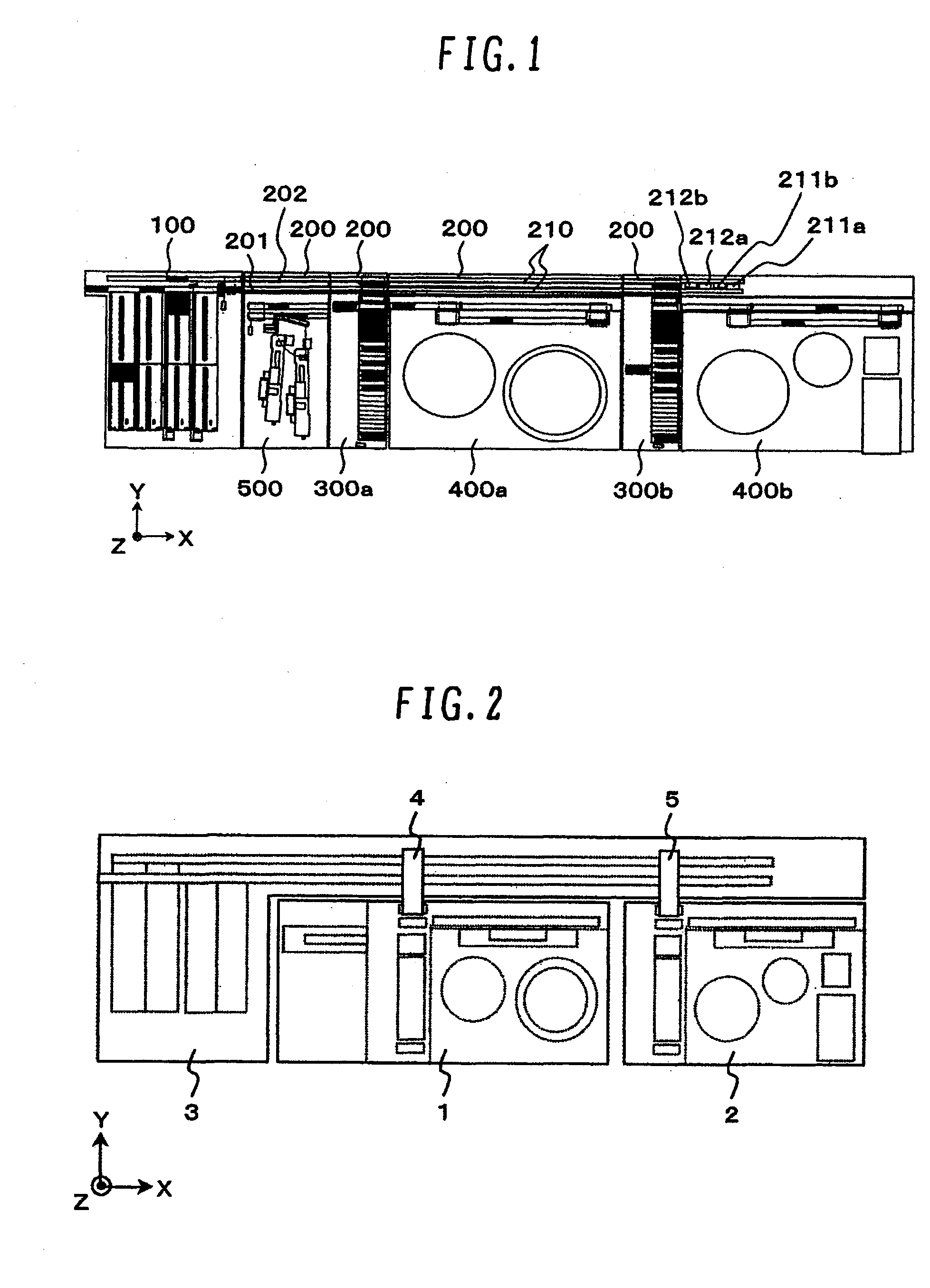
[0039]FIG. 1 is a plan view of a sample-processing system according to an embodiment of the present invention. The system shown as an example in FIG. 1 includes: a sampler unit 100 for loading and storing a sample rack; a rack conveyance unit 200 for conveying the sample rack between the sampler unit and functional modules; buffer units 300a and 300b each disposed along the rack conveyance unit 200, for transferring the sample rack to and from the rack conveyance unit 200 and for causing temporary standby of the sample rack; functional modules 400a and 400b each paired with the buffer unit 300a or 300b and located to the right thereof; and a supplemental module 500 located to the right of the buffer unit 300a.

[0040]FIG. 2 shows the system of FIG. 1 in functionally classified form. In this case, constituent elements of the system can be classified into a functional block 1 including the buffer unit 300a, the fu...


PUM


Abstract

Disclosed herein is a sample-processing system that can improve total system processing efficiency, and reduce a sample-processing time, by establishing a functionally independent relationship between a rack conveyance block with rack supply, conveyance, and recovery functions, and a processing block with sample preprocessing, analysis, and other functions. A buffer unit with random accessibility to multiple racks standing by for processing is combined with each of multiple processing units to form a pair, and the system is constructed to load and unload racks into and from the buffer unit through the rack conveyance block so that one unprocessed rack is loaded into the buffer unit and then upon completion of process steps up to automatic retesting, unloaded from the buffer unit. Functional dependence between any processing unit and a conveyance unit is thus eliminated.

Description

BACKGROUND OF THE INVENTION[0001]1. Field of the Invention[0002]The present invention relates generally to sample-processing systems. More particularly, the invention relates to a sample-processing system suitable for efficient operation of a plurality of analyzers different in functionality and in processing capabilities and interconnected using a conveyor line to convey sample racks.[0003]2. Description of the Related Art[0004]Analytical results on blood plasma, serum, urine, and other biological samples provide large volumes of useful information for diagnosing medical conditions, and there are a large number of conventional techniques relating to analyzers intended for automatic processing of such biological samples.[0005]JP-A-10-19899, for example, discloses a technique on which is based an automatic analyzer that includes a plurality of analytical units each equipped with transfer means for loading a rack into the analytical unit, with transfer means provided independently of ...

Claims


Application Information

Patent Timeline
IPC IPC(8): B01J19/00
CPCG01N35/026G01N35/04Y10T436/115831G01N2035/0467Y10T436/113332G01N2035/0462G01N35/10G01N2035/00326G01N2035/0465
Inventor TOKIEDA, HITOSHITAKAGI, YOSHIMITSUSHIBUYA, TAKESHIAKUTSU, MASASHI
Owner HITACHI HIGH-TECH CORP
Why Eureka
Try Eureka