Molding apparatus, method of manufacturing molding apparatus, and molding method

Inactive Publication Date: 2009-07-02
SUMITOMO HEAVY IND LTD
View PDF1 Cites 6 Cited by
  • Summary
  • Abstract
  • Description
  • Claims
  • Application Information

AI Technical Summary

Benefits of technology

[0027]In the molding apparatus according to the first aspect of the present invention, the inner wall of the flow pass is defined cooperatively by the surface of the first member and the surface of the second member. Namely, the flow pass is formed by adhering the surface of the first member to the surface of the second member. Since the flow pass is formed neither in the first member nor in the second member, the flow pass can be formed easily even if the first or second member is made small.
[0028]In the molding apparatus according to the second aspect of the present invention, the flow pass for heat exchange with the second member is disposed between the first member and design surface. The design surface can therefore be cooled efficiently. The heater heats the surface layer of the second member on the design surface side, from the inside of the second member. It is therefore easy to maintain the design surface at a desired temperature or higher, while the molding pattern formed on the design surface is transferred to molding material.
[0029]In the molding apparatus according to the third aspect of the present invention, the shortest distance from the heater to design surface is adjust

Problems solved by technology

If a temperature of molding material injected into the die lowers and fluidity is degraded, concave portions of a molding pattern cannot be filled properly with the molding material, and a transfer precision cannot be increased.
Therefore, the design surface cannot be cooled effic

Method used


Image

  • Molding apparatus, method of manufacturing molding apparatus, and molding method
  • Molding apparatus, method of manufacturing molding apparatus, and molding method
  • Molding apparatus, method of manufacturing molding apparatus, and molding method

Examples


first embodiment

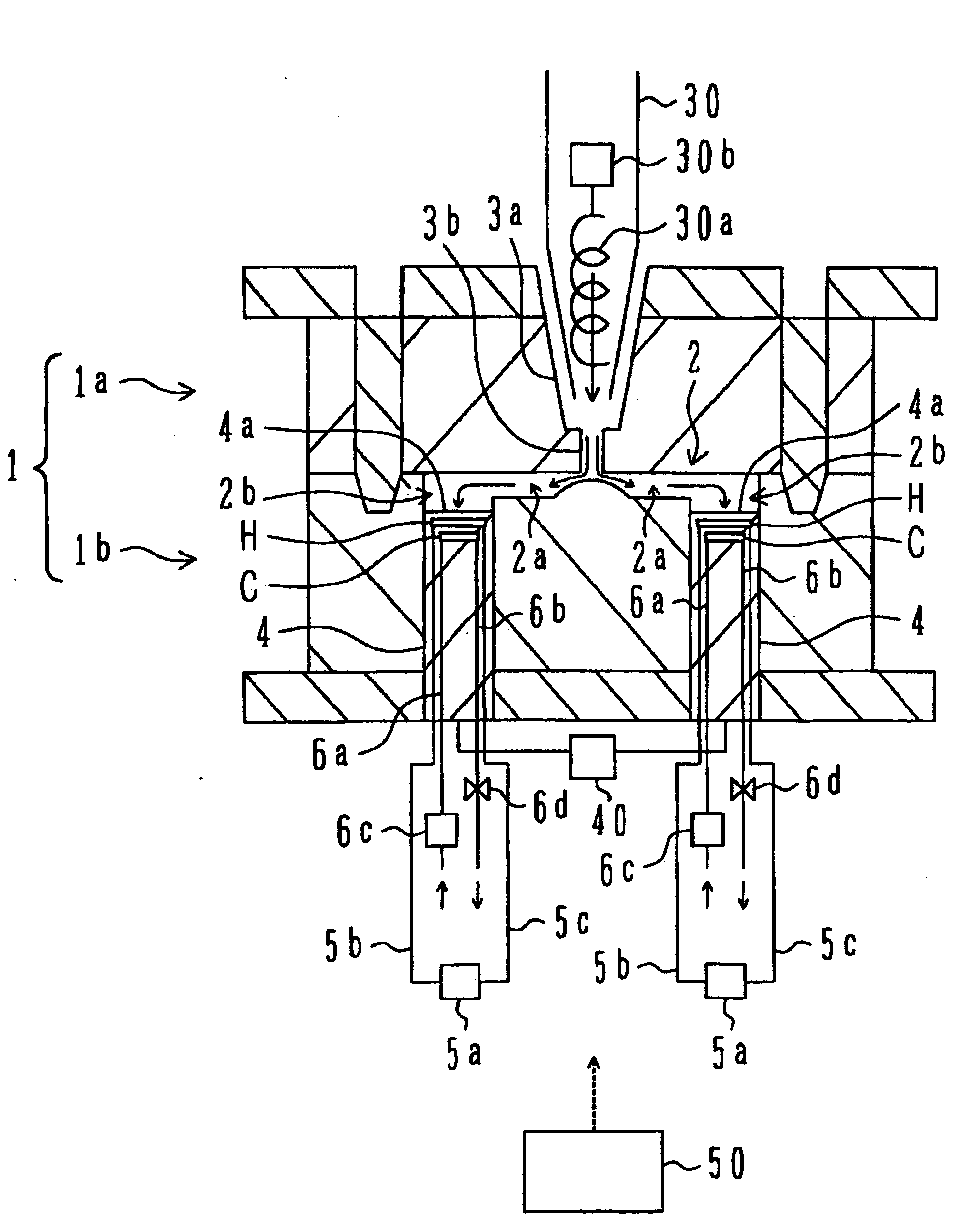
[0043]FIG. 1 is a schematic cross sectional view of a molding apparatus according to the present invention. A die 1 is constituted of a fixed die 1a and a movable die 1b. In a state that the die 1 is closed, a space 2 including a runner 2a and a cavity 2b is defined between the fixed die 1a and movable die 1b.

[0044]As a screw 30a disposed in a cylinder 30 is rotated, molding material in a melted state is ejected from the cylinder 30. Molding material is resin such as polycarbonate. A drive mechanism 30b drives the screw 30a. The molding material ejected from the cylinder 30 is injected into the space 2 via a nozzle 3a and a spool 3b formed in the fixed die 1a. The cavity 2b is filled with the molding material injected into the space 2, via the runner 2a.

[0045]A plunger 4 is assembled in the movable die 1b, the plunger 4 having a design surface 4a formed with a molding pattern. The design surface 4a defines a portion of the inner wall of the cavity 2b. A drive mechanism 40 moves th...

second embodiment

[0109]Next, a molding apparatus of the second embodiment will be described. FIG. 8A is a schematic diagram showing a molding apparatus (electrically operated injection molding apparatus). An injection molding apparatus 340 is constituted of an injection apparatus 350 and a die clamping apparatus 370.

[0110]The injection apparatus 350 has a heating cylinder 352 and a hopper 352 for supplying resin to the heating cylinder 351. A screw 353 is disposed in the heating cylinder 351, freely moving backward and forward and freely rotating. The back end of the screw 353 is rotatively supported by a support member 354. A weighing motor 355 such as a servo motor is mounted on the support member 354 as a drive part. Rotation of the weighing motor 355 is transmitted to the driven screw 353 via a timing belt 356 mounted on an output shaft 361 of the weighing motor 355. A detector 362 is directly coupled to the back end of the output shaft 361 of the weighing motor 355. The detector 362 detects a r...


PUM

PropertyMeasurementUnit
Distanceaaaaaaaaaa
Distanceaaaaaaaaaa
Distanceaaaaaaaaaa

Abstract

A molding apparatus includes: a heat insulting member; a heat conducting member disposed in a partial surface area of the heat insulating member, the heat conducting member being made of material having a thermal conductivity higher than that of the heat insulating member and including a design surface formed with a molding pattern on a surface on an opposite side to the heat insulating member; a heater for heating a surface layer of the heat conducting member on the design surface side, from the inside of the heat conducting member; and a flow pass disposed between the heat insulating member and design plate and flowing a thermal medium for thermal exchange with the heat conducting member.

Description

BACKGROUND OF THE INVENTION[0001]A) Field of the Invention[0002]The present invention relates to a molding apparatus and a method of manufacturing a molding apparatus, and more particularly to a molding apparatus capable of heating or cooling a design surface formed with a molding pattern and a method of manufacturing the molding apparatus. The present invention relates also to a molding method using a molding apparatus having a flow pass for flowing a medium to cool a design surface.[0003]B) Description of the Related Art[0004]Techniques are widely known according to which a die is filled with melted molding material and a molding pattern formed on the design surface of the die is transferred to the molding material.[0005]If a temperature of molding material injected into the die lowers and fluidity is degraded, concave portions of a molding pattern cannot be filled properly with the molding material, and a transfer precision cannot be increased. If the die is heated and a temperat...

Claims


Application Information

Patent Timeline
IPC IPC(8): B29C33/42B29C35/02B29C43/52
CPCB29C45/7312B29C33/02B29C33/04B29C45/73B29C45/76
Inventor TOKUNOU, RYUICHIHIRATA, TORU
Owner SUMITOMO HEAVY IND LTD
Why Eureka
Try Eureka