Motor control apparatus, vehicle fan drive apparatus, and motor control method

a motor control and motor control technology, applied in the direction of electronic commutation motor control, motor/generator/converter stopper, dynamo-electric converter control, etc., can solve the problem of reducing the developed torque, large difference between the highest and lowest operating environment temperatures, and large flow in the motor

Active Publication Date: 2009-07-02
DENSO CORP
View PDF8 Cites 36 Cited by
  • Summary
  • Abstract
  • Description
  • Claims
  • Application Information

AI Technical Summary

Benefits of technology

[0013]A first object of the present invention is to provide a motor control apparatus and a motor control method, which are capable of surely starting while suppressing abnormal noise even when the driving of a brushless DC motor is controlled by a sensorless control system using a drive signal whose energization angle is less than 180°, and a vehicle fan drive apparatus having the motor control apparatus.
[0014]A second object of the present invention is to provide a motor control apparatus, a motor control method, and a vehicle fan drive apparatus having the motor control apparatus, which are capable of surely driving the motor even when it is determined that shift to the sensorless control is difficult after the brushless DC motor starts.
[0018]Under the above circumstances, in the case of starting the motor from the stop state or from the low-speed rotating state, the forced commutation of a drive signal whose applied voltage amplitude to the motor gently changes by a complementary PWM control is performed. As a result, the voltage level and the frequency of the drive signal is appropriately adjusted while suppressing the occurrence of the drive sound, thereby making it possible to give a torque for surely starting the motor.

Problems solved by technology

For example, in a motor that is mounted in a vehicle, a difference between the highest and lowest operating environment temperatures is very large.
As a result, even if a voltage that is applied to the motor has the same level, a current that flows in the motor is reduced, thereby also reducing the developed torque.
Accordingly, in the case where the developed torque is reduced by a rise of the atmospheric temperature when the forced commutation is performed at the time of start, it is likely that a rotor does not follow the commutation speed of the drive circuit side, and fails to start.
In the forced commutation that is caused by the drive signal whose voltage waveform is the rectangular waveform in which the energization angle is less than 180°, the vibrations of the motor which is attributable to the torque ripple increase, to thereby generate an abnormal noise at the time of start.
Also, the motor that is mounted in, for example, a vehicle, particularly in an engine compartment, is very severe in the operating environment, and the magnetic flux of a rotor magnet is deteriorated under the high-temperature environment.
The magnetic flux is deteriorated when a rotor magnet is rusted while the motor is used for a long period of time.
However, in the above system, when the failure of shifting to the sensorless control is caused by the environment or the secular change, the problem cannot be essentially solved by merely changing the control mode, and there is a risk that the restart is repeated.
Then, when the applied voltage increases or the rotation speed increases to execute the forced commutation by a conventional rectangular waveform drive signal, the noise at the time of driving becomes large.
As a result, a vehicle passenger may feel uncomfortable.

Method used


Image

  • Motor control apparatus, vehicle fan drive apparatus, and motor control method
  • Motor control apparatus, vehicle fan drive apparatus, and motor control method
  • Motor control apparatus, vehicle fan drive apparatus, and motor control method

Examples


first embodiment

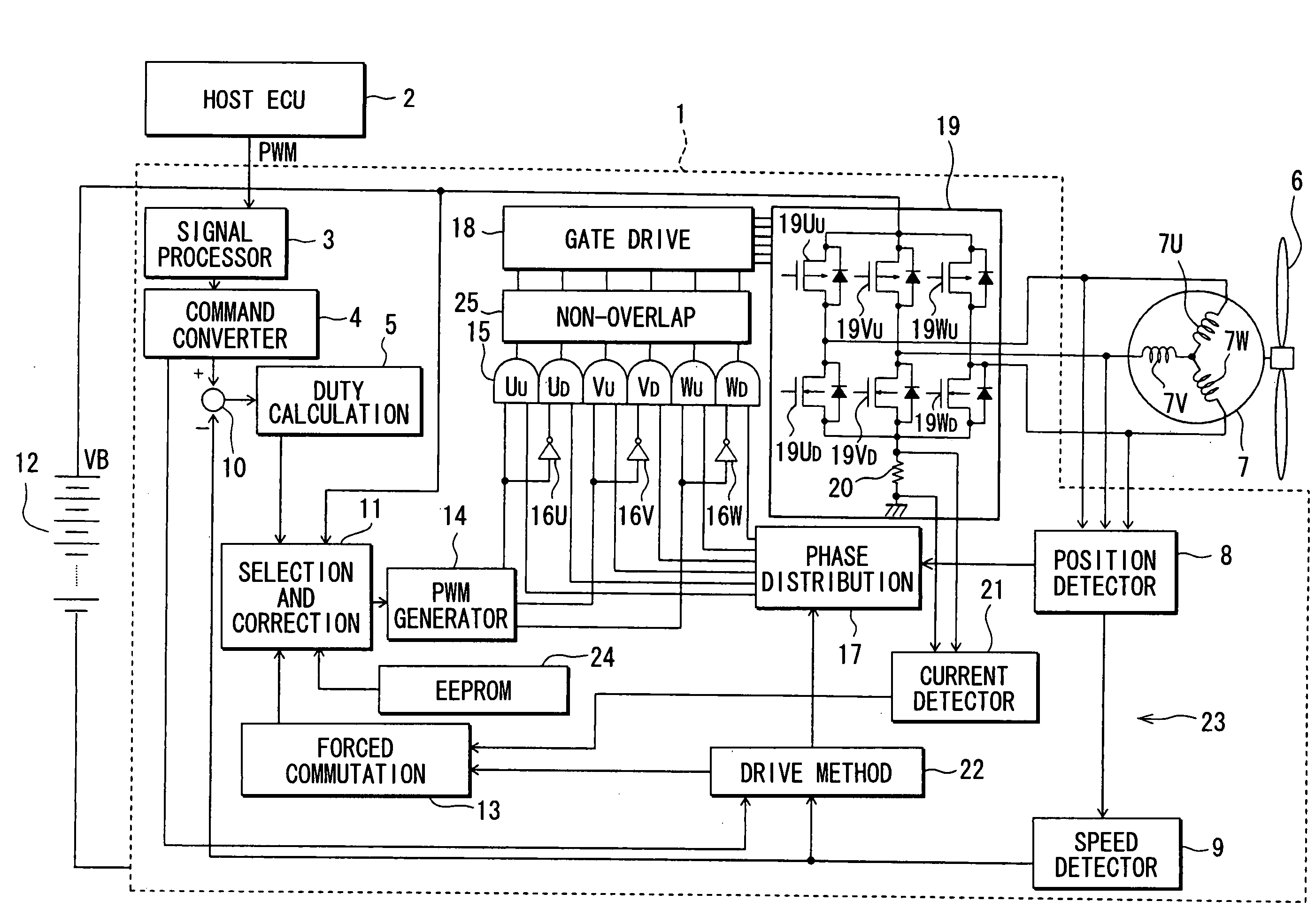
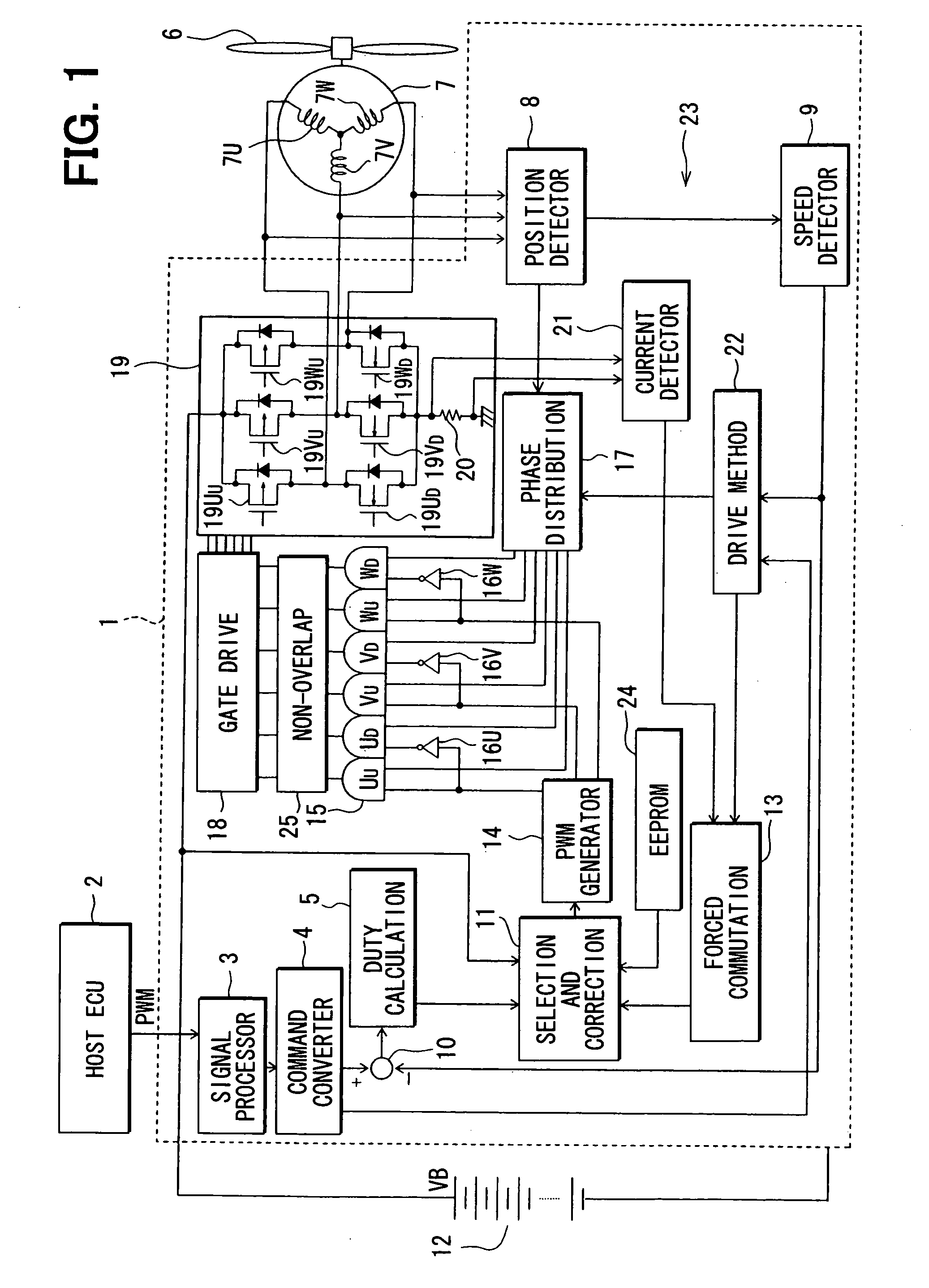
[0042]Referring first to FIG. 1 showing a first embodiment, a motor control apparatus is configured as a fan drive apparatus 1 for driving a fan motor 7 mounted in a vehicle by energizing or exciting the fan motor 7 under a PWM control. The fan motor 7 is a three-phase brushless DC motor. Upon receiving a rotation speed command of a fan which is supplied as a PWM signal from a host control unit 2 such as a host ECU (electronic control unit), the fan drive apparatus 1 converts the PWM signal after signal processing by a signal processor circuit 3 into a voltage signal corresponding to the duty of the PWM signal, and outputs the voltage signal to a rotation speed command converter circuit 4. Upon receiving output signals from, for example, a water temperature sensor (NOt shown) that detects a water temperature within a radiator, or a vehicle speed sensor that detects the vehicle speed, the host control unit 2 outputs the rotation speed command according to those detection results.

[004...

second embodiment

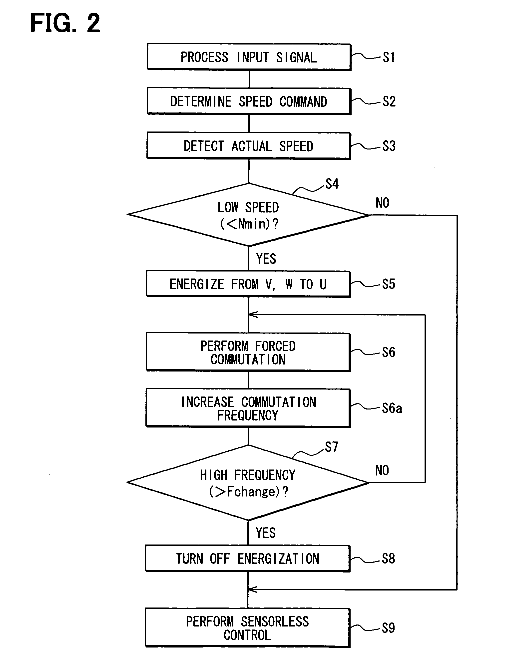
[0070]The second embodiment may be configured in the similar manner as the first embodiment. In this embodiment, however, the current detector circuit 21 is used additionally in comparison to the first embodiment. As shown in FIG. 5 corresponding to FIG. 2, when the rotor is positioned with the DC energization in S5, the duty command selection circuit 11 detects an actual current value that flows in the shunt resistor 20 in this situation through the current detector circuit 21 (S11). Then, the voltage amplitude (maximum) of the pseudo sinusoidal wave which is a start drive signal is variably set according to the amplitude of the current value.

[0071]That is, since the resistance of the winding wires of the motor 7 changes according to the ambient temperature, the current reflects the winding resistance at that time according to the voltage that is applied to the winding wires at the time of positioning. Accordingly, when the voltage amplitude of the start drive signal is set accordi...

third embodiment

[0072]The third embodiment may be configured in the similar manner as the first embodiment. In the third embodiment, however, the voltage of the start drive signal is gradually increased (S14). That is, the maximum of the amplitude that changes in the sinusoidal configuration increases every time S14 is executed. For example, the maximum is increased by each 1% of the upper limit until reaching the upper limit of the applied voltage. With the above configuration, it is possible to start the motor more smoothly and surely.


PUM


Abstract

A motor control apparatus has a start control section. When the motor control apparatus receives a motor start command from a host control unit when a motor is in a stop state or a low-speed rotating state where a sensorless control cannot be applied, the control section starts the motor that rotates a vehicle fan by a forced commutation which supplies a pseudo sinusoidal drive signal caused by a complementary PWM control. Thereafter, the motor control apparatus switches over to a sensorless control using a rectangular wave drive signal at an energization angle of lower than 180°.

Description

CROSS REFERENCE TO RELATED APPLICATION[0001]The present application is based on and incorporates herein by reference Japanese Patent Applications No. 2007-339026 filed on Dec. 28, 2007, No. 2008-209731 filed on Aug. 18, 2008 and No. 2008-209732 filed on Aug. 18, 2008.FIELD OF THE INVENTION[0002]The present invention relates to a motor control apparatus and a motor control method, which control the driving of a brushless DC motor without using a position sensor and the like, and a vehicle fan drive apparatus having the motor control apparatus.BACKGROUND OF THE INVENTION[0003]Control systems for driving a brushless DC motor without using a position sensor such as a hole IC are classified into two (first and second) systems. In the first system, an energization (current supply) angle is less than 180°. In the second system that drives the brushless DC motor with a sinusoidal wave voltage, the energization angle is 180°.[0004]The first control system, in which the energization angle is ...

Claims


Application Information

Patent Timeline
Patent Type & Authority Applications(United States)
IPC IPC(8): H02P1/50H02H7/093
CPCH02P2209/07H02P6/20
Inventor KANAMORI, ATSUSHI
Owner DENSO CORP
Why Eureka
Try Eureka