Hearing device and method for a wireless receiving and/or sending of data

Active Publication Date: 2009-07-02
OTICON
View PDF7 Cites 42 Cited by
  • Summary
  • Abstract
  • Description
  • Claims
  • Application Information

AI Technical Summary

Benefits of technology

[0014]One or more of the electrical conductors in the RITE cord (or in the interconnecting tube of standard BTE type instruments) may be used as or in an antenna for wireless applications in the hearing instrument. This saves space in the device and reduces cost. Further, as the size of the coupling element allows for a better adaptation to a wavelength of the electromagnetic signal used for transmitting the data, the efficiency and bandwidth of the antenna is improved in comparison to known antenna solutions inside the hearing device.
[0016]It was found that an improvement of efficiency that can be achieved by using the RITE wires compared to an internal loop antenna with an area of maximum 100 mm2 is about 6 dB at 1 GHz, which is a significant improvement from the estimated best case efficiency for the internal loop antenna of −16 dB.
[0018]According to another embodiment said electrically conducting element is adapted for carrying said signal upon transmission to said output transducer. Here, the same elements or wires are used as part of the antenna and as a transmission means for the signal to be outputted at the same time, which results in a design which is easy and simple to implement.

Problems solved by technology

Hearing instruments, in particular hearing aids, are very dense applications and when integrating wireless applications, it may sometimes be difficult to find sufficient space for required or desired antenna components.
However, common hearing instruments are typically much smaller than the wavelength in the appropriate frequency bands, which has a disadvantageous effect on the efficiency and bandwidth of the antennas build into the common hearing devices.

Method used


Image

  • Hearing device and method for a wireless receiving and/or sending of data
  • Hearing device and method for a wireless receiving and/or sending of data
  • Hearing device and method for a wireless receiving and/or sending of data

Examples


first embodiment

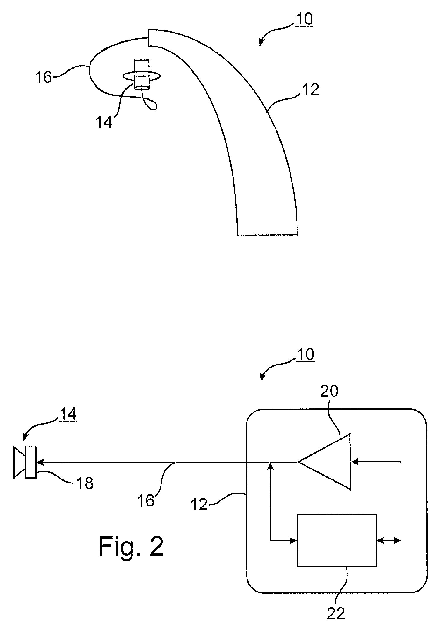
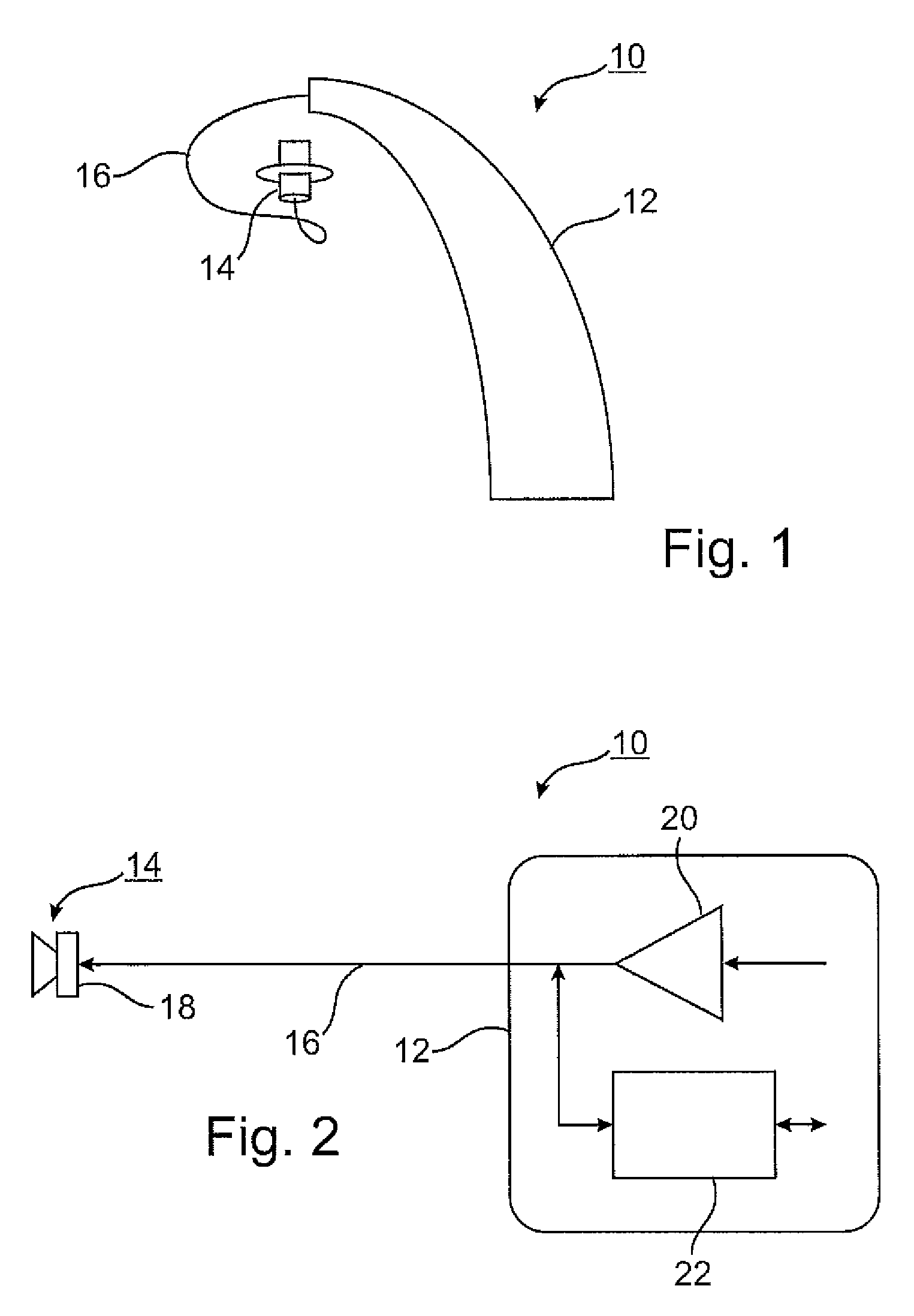
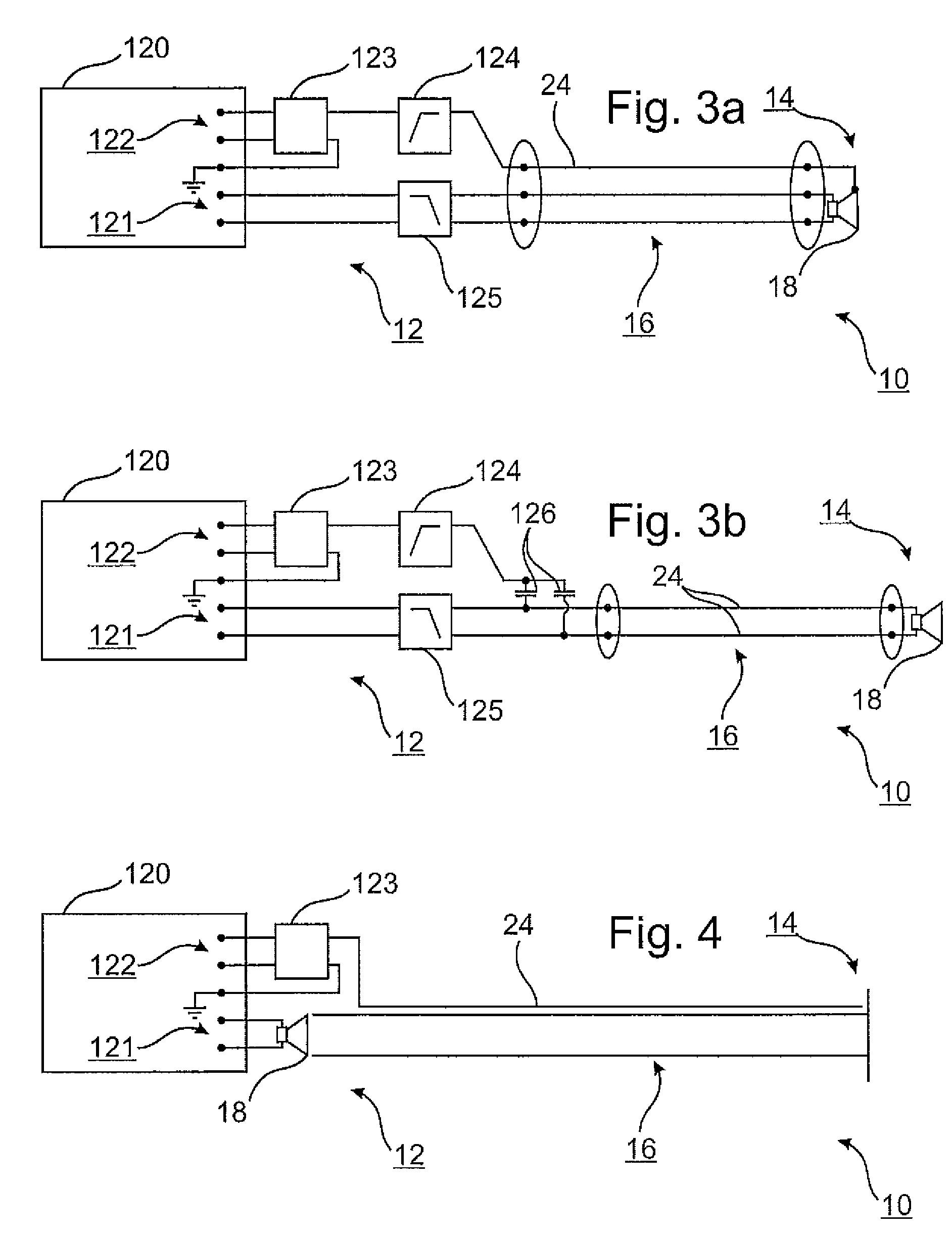
[0044]FIG. 3a shows a schematic block diagram of a hearing device according to the present invention. The hearing device 10 comprises a first portion 12, a second portion 14 and a coupling element 16. The first portion 12 of the hearing device 10 includes a printed circuit board (PCB) 120 for realizing the primary features of the hearing device 10, e.g. the processing and generation of the signal to be provided to the user, audio signal connections 121, RF signal connections 122, a balun 123, a high-pass filter 124 and a low-pass filter 125. Further, the PCB 120 includes a wireless interface (not shown). The low-pass filter 125 is coupled to audio signal connections 121 of the PCB 120. The balun 123 is coupled to RF-signal connections 122 of the PCB 120. The balun 123 is further coupled to a ground connection and to the high-pass filter 124. The low-pass filter 125 and the high-pass filter 124 are coupled to wires of the coupling element 16, wherein the high-pass filter 124 is coupl...

second embodiment

[0047]FIGS. 5a and 5b show more detailed schematic block diagrams of a particular implementation according to the first and second embodiment of the present invention shown in FIG. 3a and FIG. 3b. The balun 123 is realized in form of a transformer 123, wherein the high-pass filter 124 comprises a capacitor and a inductance coupled in a suitable way. The low-pass filter 125 comprises inductances in series with the signal lines and a capacitor coupling the signal lines.

[0048]FIG. 6 shows a flow chart of a method according to the present invention. The method for a wireless receiving and / or sending of data in a hearing device according to the present invention comprises the steps of providing (30) an electrically conducting element in said coupling element, arranging (32) said first portion at a user of said hearing device, arranging (34) said second portion in an ear canal of said user, and receiving (36) and / or sending data by means of said electrically conducting element. The order ...


PUM


Abstract

The present invention is related in particular to means for a wireless communication to and from a hearing device (10) comprising a first portion (12) adapted for being arranged at a user and for providing a signal, an output transducer (18) for converting said signal to an acoustic output and a second portion (14) adapted for being arranged in an ear canal of said user and for providing said acoustic output to said user and further related to a method for a wireless receiving and / or sending of data in a hearing device (10). In order to provide such a hearing device (10) with sufficient characteristics regarding the ability to send and / or receive data in a wireless manner using desired frequencies without a need for additional external antenna solutions or for a size not meeting the current requirements of smallness for hearing devices a hearing device (10) it is proposed, further comprising a coupling element (16) coupling said first portion (12) and said second portion (14), an antenna, and a wireless interface (22) for receiving and / or sending data by means of said antenna, wherein said coupling element (16) comprises an electrically conducting element (24) coupled to said wireless interface (22), wherein said electrically conducting element (24) is at least a part of said antenna. A corresponding method and use of a hearing device is also proposed.

Description

TECHNICAL FIELD[0001]The present invention is related to a hearing device comprising a first portion adapted for being arranged at a user and for providing a signal, an output transducer for converting said signal to an acoustic output and a second portion adapted for being arranged in an ear canal of said user and for providing said acoustic output to said user. The invention is in particular related to means for a wireless communication to and / or from such a hearing device. The invention is further related to a method of wirelessly receiving and / or sending of data in a hearing device and to the use of a hearing device.BACKGROUND ART[0002]Hearing aids for compensating a wearer's hearing loss are well known. The present invention is particularly related to such kinds of hearing devices. However, the present invention may also be implemented in other types of listening devices, hearing instruments or hearing devices which comprise a connecting element between two physical parts of th...

Claims


Application Information

Patent Timeline
IPC IPC(8): H04R25/00
CPCH04R1/1016H04R25/558H04R2420/07H04R2225/63H04R2225/51H04R25/554H04R2225/0213
Inventor KNUDSEN, OVEHENRIKSEN, POULBODVARSSON, THORVALDUR OIL
Owner OTICON
Why Eureka
Try Eureka