Non-dispersive UWB antenna apparatus using multi-resonance, and method for manufacturing the same

Inactive Publication Date: 2009-07-09
ELECTRONICS & TELECOMM RES INST
View PDF3 Cites 21 Cited by
  • Summary
  • Abstract
  • Description
  • Claims
  • Application Information

AI Technical Summary

Benefits of technology

[0013]Therefore, an object of the present invention is to provide a non-dispersive UWB antenna using multi-resonance, which can obtain a UWB characteristic through the multi-resonance by c

Problems solved by technology

However, the related art antenna can satisfy the return loss characteristic, but it is difficult to obtain an omni-directional pattern due to an asymmetric str

Method used


Image

  • Non-dispersive UWB antenna apparatus using multi-resonance, and method for manufacturing the same
  • Non-dispersive UWB antenna apparatus using multi-resonance, and method for manufacturing the same
  • Non-dispersive UWB antenna apparatus using multi-resonance, and method for manufacturing the same

Examples


Embodiment Construction

[0024]Hereinafter, specific embodiments will be described in detail with reference to the accompanying drawings.

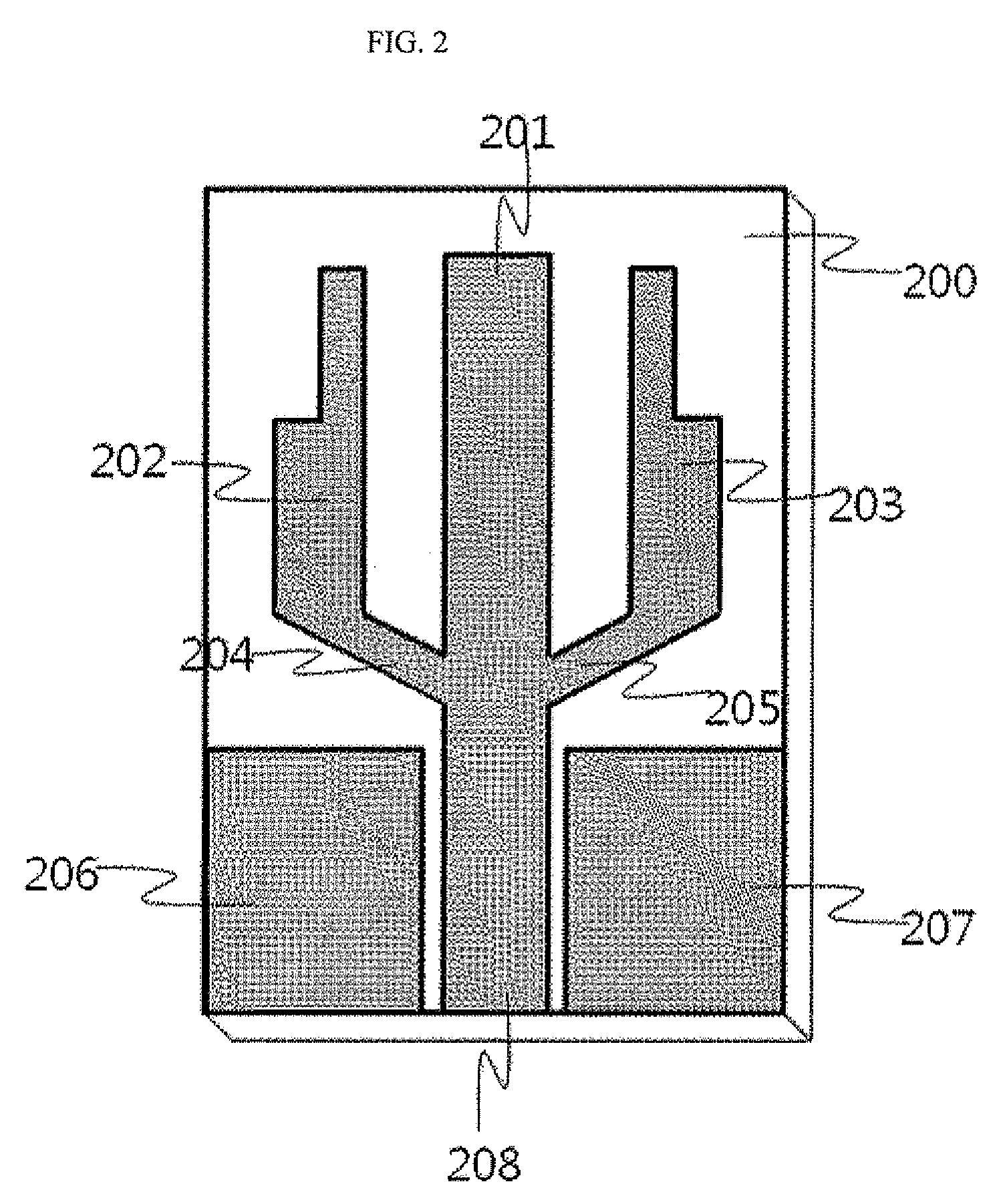
[0025]FIG. 2 is a sectional view of a non-dispersive UWB antenna using multi-resonance according to an embodiment of the present invention.

[0026]Referring to FIG. 2, the non-dispersive UWB antenna using multi-resonance includes a monopole radiation patch 201, open stubs 202, 203, 204 and 205, and a CPW feed line 208, which are disposed on a one surface of a dielectric substrate 200.

[0027]In this embodiment, the dielectric substrate 200 is an FR-4 epoxy (εr=4.5, tan δ=0.025) substrate having a size of 20×30 mm2 and a height of 1.6 mm, and the monopole radiation patch 201 is disposed in the center of the upper surface of the FR-4 substrate 200. The non-dispersive UWB antenna provides a multi-resonance mode by symmetrically connecting the open stubs 202, 203, 204 and 205 to left and right sides of the monopole radiation patch 201. The non-dispersive UWB antenna has a UWB char...


PUM

PropertyMeasurementUnit
Angleaaaaaaaaaa
Angleaaaaaaaaaa
Frequencyaaaaaaaaaa

Abstract

Provided is a non-dispersive UWB antenna using multi-resonance, which can obtain a UWB characteristic by combining a monopole radiation patch and stepped open stubs, and can obtain an improved non-dispersion characteristic by using a symmetrical structure of the monopole radiation patch and the stepped open stubs. The non-dispersive UWB antenna includes a dielectric substrate, a monopole radiation patch disposed in the center of the top surface of the dielectric substrate, stepped open stubs connected to the monopole radiation patch to induce multi-resonance, a CPW ground plane, and a CPW feed line connected to the monopole radiation patch. By using the monopole radiation patch, the stepped open stubs, and the CPW feed line, the non-dispersive UWB antenna can obtain the omni-directional radiation pattern in the frequency range (3.1-4.9 GHz) required by the system.

Description


Claims


Application Information

Patent Timeline
Owner ELECTRONICS & TELECOMM RES INST
Why Eureka
Try Eureka