Location measuring device and method

a technology of location measurement and measuring device, which is applied in the direction of instruments, cameras, image enhancement, etc., can solve the problems of inability to track, inaccurate measurement, and the inability to use the least squares method, so as to shorten the convergence time of measured results, accurate selection of taking locations, and high accuracy

Active Publication Date: 2009-07-09
KK TOPCON
View PDF9 Cites 54 Cited by
  • Summary
  • Abstract
  • Description
  • Claims
  • Application Information

AI Technical Summary

Benefits of technology

[0010]Here, the robust estimation is a method that may be carried out relatively easily even when observation data include those having large errors. Methods belonging to this type are for example: LMeds method, median estimation (M estimation) method, and RANSAC method. The threshold process is to compare data with a predetermined threshold and eliminate or choose data depending on their relative magnitudes. With the above arrangement, as large errors are eliminated before each estimating calculation process, calculation converges quickly and gives results of high accuracy. Incidentally, in the phrase “from the process or results of the feature point tracking section 4A” in the above paragraph, the term “process” relates to a real time process carried out while receiving the results of tracking; and the term “results” relates to a non-real time process in which tracked results are once stored for a later process.
[0026]With the above constitution, as large errors are removed before each estimating calculation step, makes calculation converge quickly and results are provided with high accuracy.

Problems solved by technology

However, there are problems as described below: If feature points have incorrect corresponding points in finding three-dimensional coordinates of the camera itself or the object, there may be cases in which the three-dimensional coordinates are not determined accurately, and moreover the solution does not converge in the process of calculation, leading to inability of tracking.
Even if model coordinates are calculated successfully and bundle adjustment is applied while they contain errors, accuracy may deteriorate due to insufficient removal of large errors.
Besides, if large errors remain or some points remain with large errors, estimating calculation using the least squares method consequently takes much time for convergence, and real time processing cannot be carried out.

Method used


Image

  • Location measuring device and method
  • Location measuring device and method
  • Location measuring device and method

Examples


first embodiment

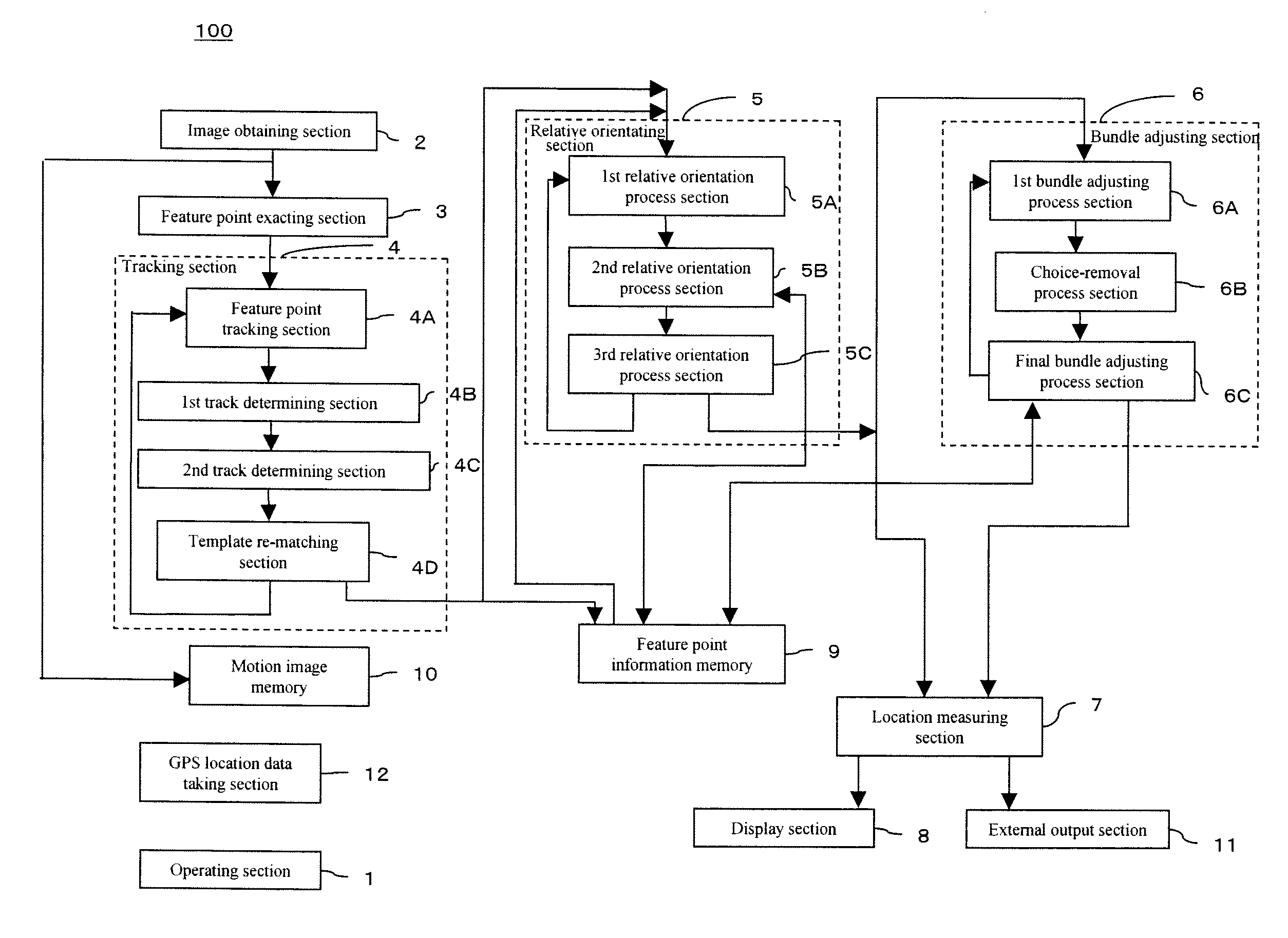
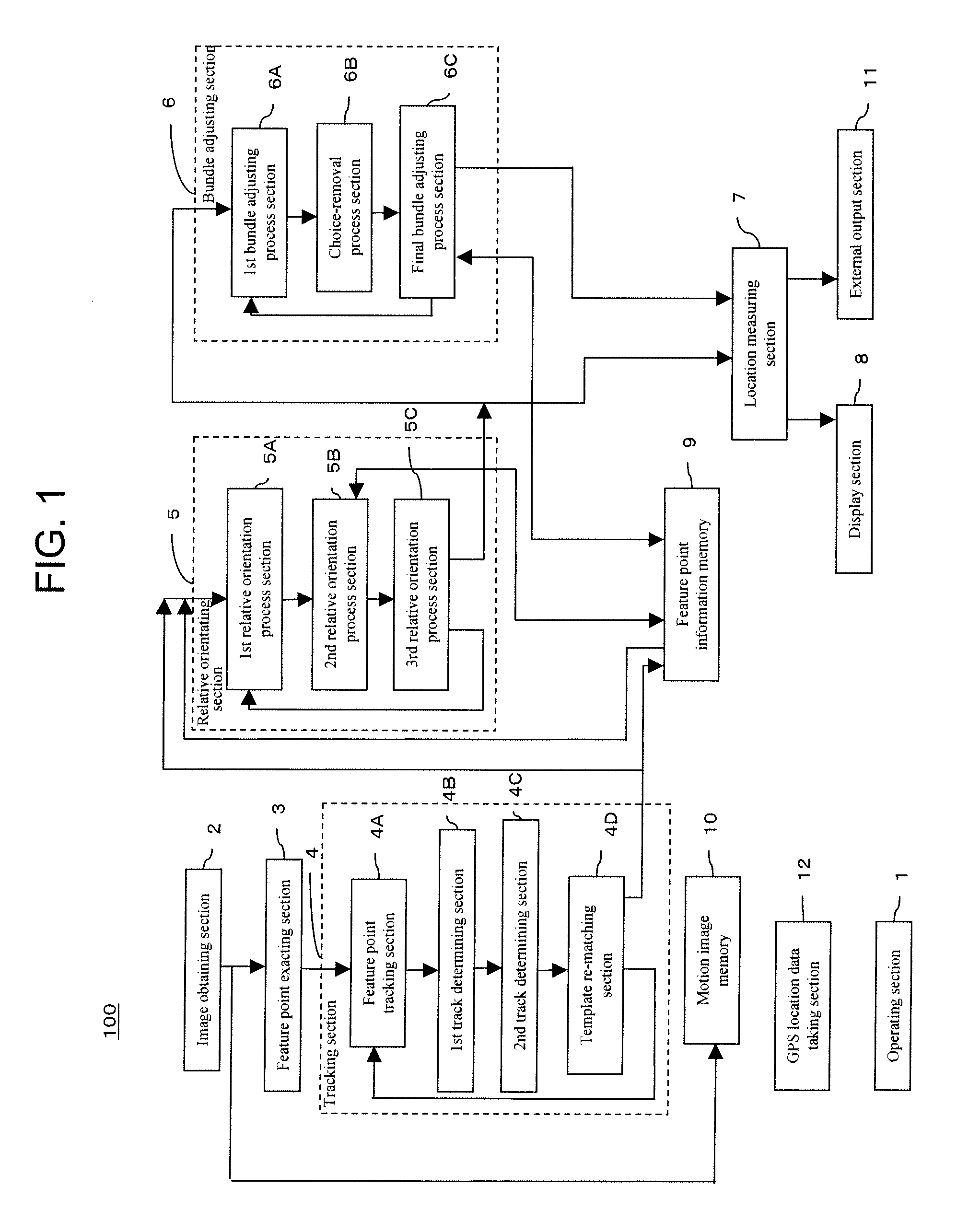
[0044]FIG. 9 shows the concept of this embodiment. This is an example in which a camera 2 is mounted on a vehicle to photograph images of an urban area as the vehicle gradually changes its location. From the results of tracking noticeable marks (feature points 101a, 101b; for example specifically noticeable points on a building) in a plurality of shot images, the location of the camera 2 or the trajectory of the vehicle is determined. While this makes it possible to display successively the locational coordinates of the camera 2 or the location of the vehicle on a vehicle navigation apparatus, supplemental use is also meaningful in areas where GPS radio waves are unavailable. When the camera 2 (hereinafter may be occasionally called the image obtaining section 2) is mounted on the vehicle as shown in the figure, the photographed image moves in various directions; lateral, vertical, and rotary directions. The photographed image often contains moving objects such as other vehicles, hu...

second embodiment

[0106]Utilization of GPS has become easy in recent years. Systems open to consumer use have been improved in accuracy due to developments of relative locationing system such as DGPS and interference locationing system such as RTK-GPS. The measurement accuracy of the latter has become in the order of several centimeters. This embodiment is to use complementally locationing data from GPS so as to improve overall accuracy and shorten measurement time.

[0107]Specifically, there is an example in which GPS data are used for tracking. This is to correlate the location data, measured with GPS, of the camera 2 corresponding to respective frames, with the frames. If the measurement output values of GPS are synchronized with the photographed image frames, a photographed frame when the GPS measurement is outputted is correlated. When they are not synchronized or cannot be synchronized, time stamps of GPS and the camera are utilized to correlate those of the time nearest to each other. Alternativ...


PUM


Abstract

To realize high speed and high precision with device and method of three-dimensional measurement by applying estimating process to points corresponding to feature points in a plurality of motion frame images. With the device and method of calculating location information through processes of choosing a stereo pair, relative orientation, and bundle adjustment and using corresponding points of feature points extracted from respective motion frame images, each process is made up of two stages. To the first process section (stages:5A and 6A), robust estimation is applied to determine estimated values of calculation parameters. In the second process section (stages:5B and 6B), corresponding points and stereo pair of large residual errors are excluded, and estimating calculation is carried out again to make measurements in three dimensions.

Description

BACKGROUND OF THE INVENTION[0001]1. Technical Field[0002]This invention relates to a location measuring device and a location measuring method. More specifically, this invention relates to such a location measuring device and a location measuring method that obtain three-dimensional coordinates of a camera or an object from motion images of the object photographed by moving the camera relative to the object.[0003]2. Related Art[0004]There is a technique to measure the location of an object or a camera itself using images of the object which the camera picks up in succession while the camera makes motion relative to the object. With this technique, a plurality of images are photographed at a distance and corresponding points between the images are tracked, a stereo pair is set up from two of the images, model images are made, and bundle adjustment is made on the basis of the plurality of images to obtain final and three-dimensional measurement results. Such a technique is disclosed f...

Claims


Application Information

Patent Timeline
Patent Type & Authority Applications(United States)
IPC IPC(8): G06K9/00
CPCG06T7/0044G06T2207/10016G06T2200/08G06T7/0071G06T7/579G06T7/74
Inventor KOCHI, NOBUOANAI, TETSUJIOTANI, HITOSHI
Owner KK TOPCON
Why Eureka
Try Eureka