Non-powered, aero-assisted pre-stage for ballistic rockets and aero-assisted flight vehicles

Inactive Publication Date: 2009-07-16
USTINOV EUGENE ALEXIS
View PDF9 Cites 9 Cited by
  • Summary
  • Abstract
  • Description
  • Claims
  • Application Information

AI Technical Summary

Benefits of technology

[0016]In accordance with one aspect, the launch of a space vehicle, a rocket and/or spaceplane, is assisted by attaching it to a non-powered aircraft that has wings to provide sufficient aerodynamic lift to enable take-off at a conveniently low take-off airspeed, and control surfaces to provide flight control during launch and return to ground. The launch is conducted in the form of an aircraft-like take-off from a conventional runway. I call this aircraft a Non-powered, Aero-assisted Pre-stage (NAP). The NAP facilitates launch of the space vehicle, with propulsion provided by the space vehicle and aerodynamic lift provided by the NAP. Ample thrust from main engines of the space vehicle is combined with ample wing area of the NAP, which is not constrained by the requirement, as in prior art, to fl

Problems solved by technology

These launch structures are expensive to build and expensive to operate.
There are a limited number of them around the world, which places substantial operational limitations on access to space.
Unfortunately, this constraint requires extremely high take-off airspeed, which is incompatible with the use of runways of most conventional airfields.
This requirement for very high take-off airspeed is unrealistic since it not only greatly exceeds existing technical capabilities of conventional technologies used for the undercarriage of existing flight vehicles, but it also severely limits the choice of acceptable runways that can accommodate such operation.
In addition, Nelson's glider had no undercarriage and was dependent upon the spaceplane to provide an undercarriage, thus limiting payload diversity.
This limitation results in weaker mechanical strength a

Method used


Image

  • Non-powered, aero-assisted pre-stage for ballistic rockets and aero-assisted flight vehicles
  • Non-powered, aero-assisted pre-stage for ballistic rockets and aero-assisted flight vehicles
  • Non-powered, aero-assisted pre-stage for ballistic rockets and aero-assisted flight vehicles

Examples


first embodiment

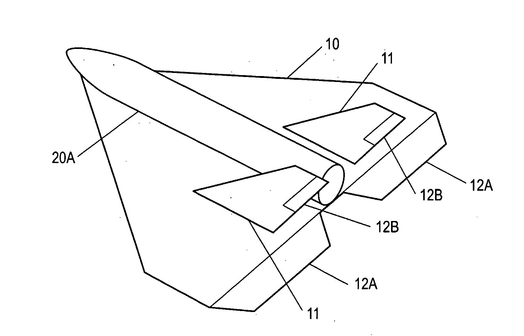
Operation—First Embodiment in Conjunction with Ballistic Rocket

[0040]Operation of first embodiment is as follows. The NAP-vehicle stack is placed on the runway. The engine of the rocket is ignited, the NAP-vehicle stack rolls-out (i.e., accelerates along the horizontal runway to take-off speed), takes off, and climbs to the separation point using propulsion from rocket. During this phase, control surfaces of the NAP are used for flight control in a conventional manner.

[0041]At the separation point, which may be at attitude of a few hundred meters, the hold-and-release mechanism separates vehicle 20A from NAP 10. After separation, NAP 10 makes a 180-degree turn, and glides back to the launch site for subsequent reuse or disposal. Vehicle 20A then proceeds along its ascent trajectory in conventional fashion.

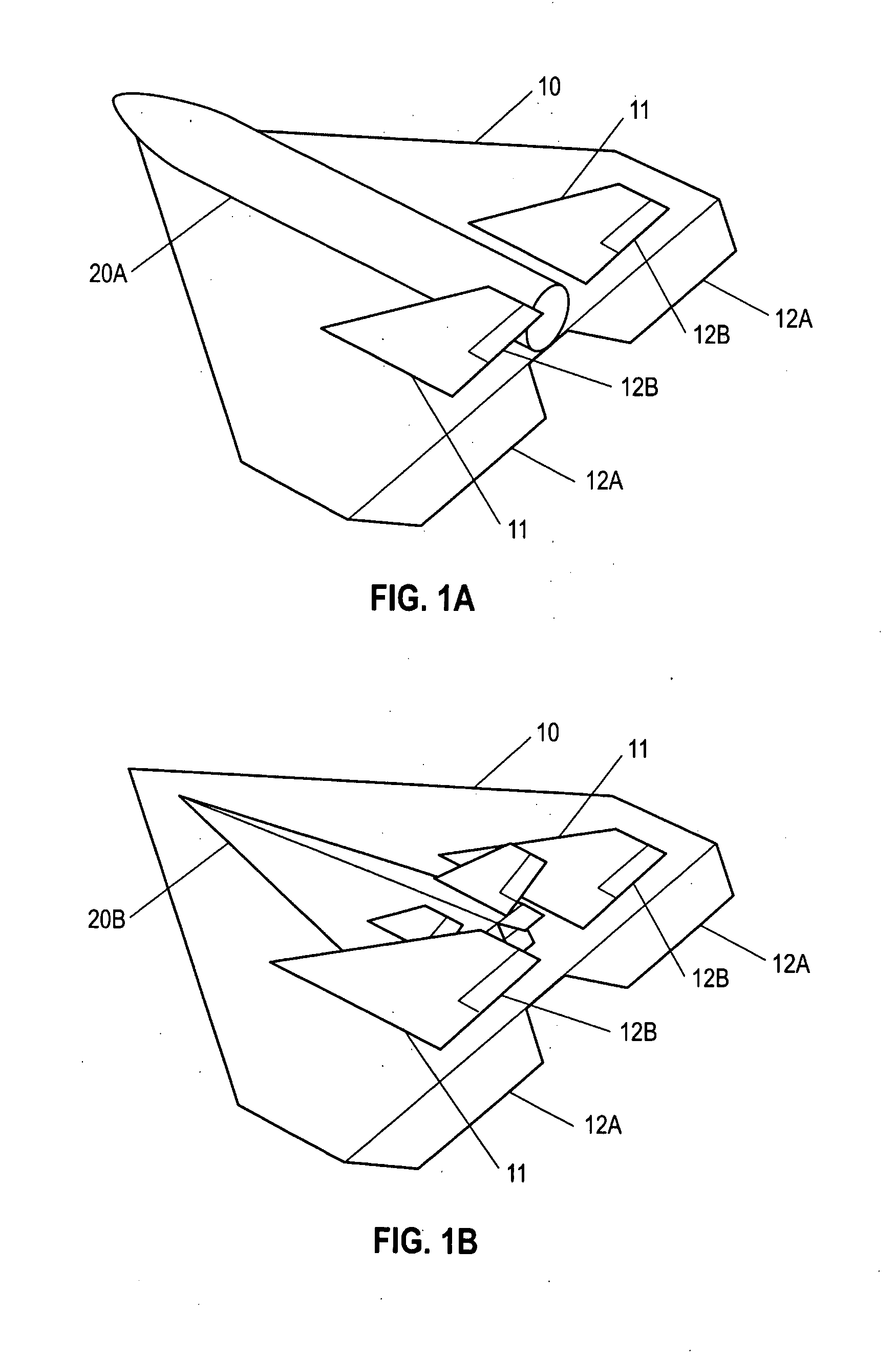
Second Embodiment—Custom Designed NAP as a Pre-Stage of a Spaceplane—FIG. 1B

[0042]FIG. 1B shows a second embodiment of NAP 10 implemented as a custom-designed delta-wing glider to ...

second embodiment

Operation—Second Embodiment in Conjunction with Spaceplane

[0046]Operation of the second embodiment of FIG. 1B with the spaceplane proceeds in essentially the same fashion as with the ballistic rocket of FIG. 1A. The NAP-vehicle stack is placed on the runway. The engine of the spaceplane is ignited, the NAP-vehicle stack rolls-out, takes off, and climbs to a separation point using propulsion from vehicle. During this phase, control surfaces of the NAP are used for flight control in a conventional manner.

[0047]At the separation point, which may be at altitude of a few hundred meters, the hold-and-release mechanism separates vehicle 20B from NAP 10. After separation, NAP 10 makes a 180-degree turn, and glides back to the launch site for subsequent reuse or disposal thereof. Vehicle 20B then proceeds along its ascent trajectory in conventional fashion.

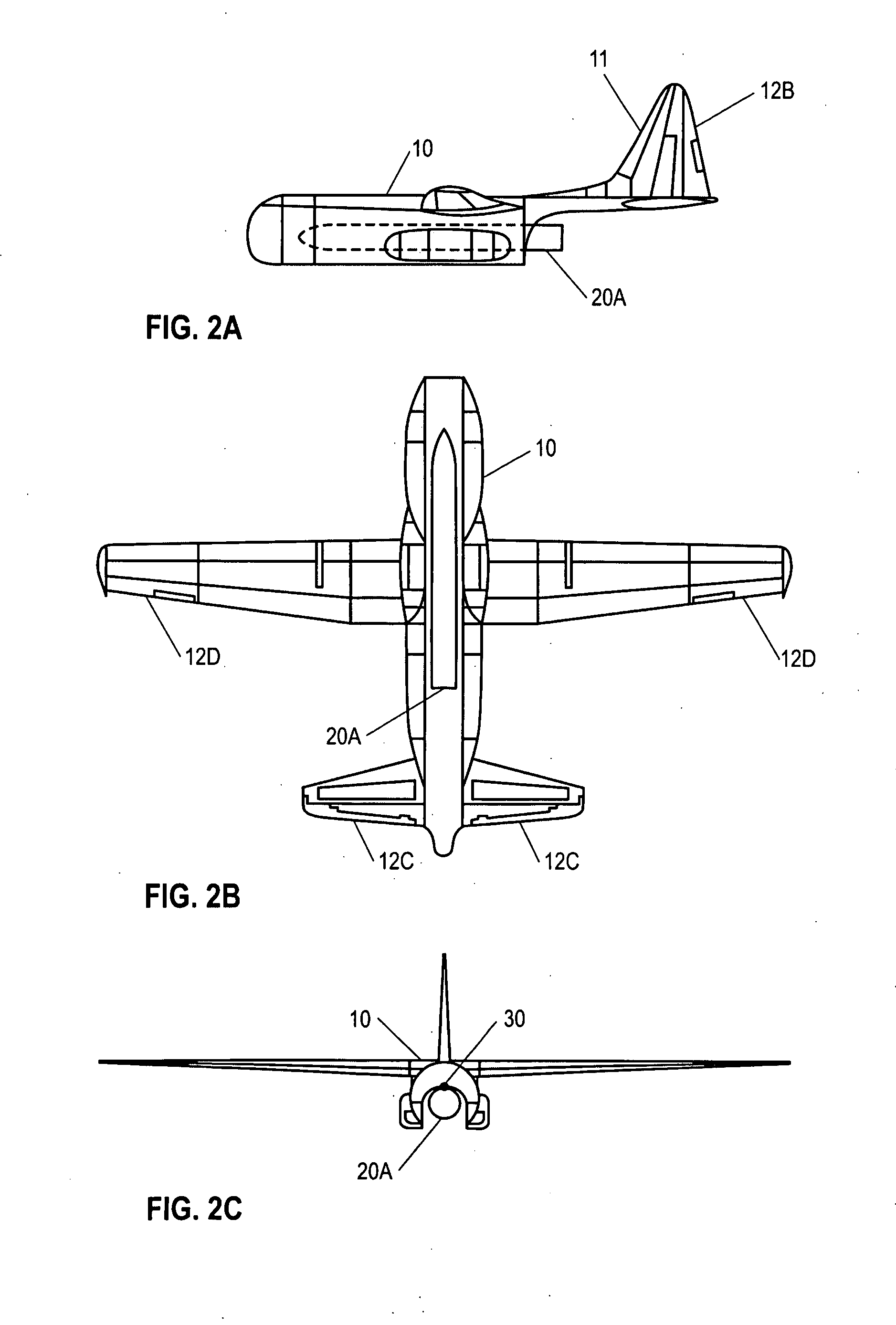
Third Embodiment, Modification of a Suitable Airplane—FIGS. 2A, 2B, and 2C

[0048]A third embodiment of the NAP is illustrated in FIGS. 2A,...

third embodiment

Operation—Third Embodiment

[0050]Operation of the third embodiment is similar to that of the first embodiment. The stack rolls-out on a conventional runway, takes off, and climbs to the separation point in a fashion conceptually identical to those of the first and second embodiments. At the separation point, hold-and-release mechanism 30 releases rocket 20A from NAP 10 and the NAP proceeds downward. Separation is assisted by the gravity component across the flight path. After separation, the operation proceeds similarly to the operation of the first embodiment: NAP 10 glides back to the launch site for subsequent reuse or disposal, and rocket 20A proceeds along its ascent trajectory in conventional fashion.

Other Embodiments—FIGS. 3A to 3C and 4A to 4C

[0051]A number of embodiments are illustrated ins FIGS. 3A, 3B, and 3C. FIG. 3A is a rear view of the NAP in the form of a delta-wing glider in conjunction with ballistic rocket carried on the upper surface of the NAP; FIG. 3B is a rear ...


PUM


Abstract

A non-powered pre-stage (10) with a commensurably large wing area is used to launch a variety of single-stage and multiple-stage space vehicles (20), such as conventional ballistic rockets and prospective spaceplanes, from conventional runways. This method of launch eliminates need in dedicated ground launch structures and/or dedicated long runways. The vehicle to be launched (20) is mated to this non-powered aero-assisted pre-stage (NAP) (10), with their flight directions aligned, using a lock-and-release mechanism (30). The resulting stack takes off like a conventional airplane using the propulsion of the vehicle and aerodynamic lift of the NAP. After the desired trajectory of the vehicle is achieved, the vehicle is separated from the NAP and continues its ascent. The NAP returns back to the surface for reuse or disposal. Thus, a wide variety of conventional airfields can be used for launch of ballistic and aero-assisted flight vehicles.

Description

CROSS-REFERENCE TO RELATED APPLICATION[0001]This application claims the benefit of provisional patent application Ser. No. 61 / 011,119, filed Jan. 15, 2008 by the present inventor.FEDERALLY SPONSORED RESEARCH [0002]Not ApplicableSEQUENCE LISTING OR PROGRAM [0003]Not ApplicableBACKGROUND OF THE INVENTION [0004]1. Field[0005]This application generally relates to the launch of flight vehicles, specifically to enabling the launch of ballistic rockets and aero-assisted flight vehicles (spaceplanes) from conventional runways, without use of, respectively, dedicated ground launch structures or dedicated runways.[0006]2. Prior Art[0007]From the dawn of Space Era through present time, all space launches—sub-orbital, orbital, and beyond—have been accomplished almost solely using ballistic (wingless) rockets launched from the ground. This approach requires dedicated ground launch structures for assembling and servicing the rockets before launch. Also, the launch structure must hold the rocket i...

Claims


Application Information

Patent Timeline
IPC IPC(8): B64C37/02
CPCB64D5/00
Inventor USTINOV, EUGENE ALEXIS
Owner USTINOV EUGENE ALEXIS
Why Eureka
Try Eureka