Speaker device and speaker unit

a speaker device and speaker technology, applied in the direction of deaf-aid sets, transducer details, electrical transducers, etc., can solve the problems of the heat generated on the voice coil cannot be easily dissipated, and the air temperature in the sealed space to become relatively high, so as to achieve heat dissipation, reduce sound quality, and simple structure

Inactive Publication Date: 2009-07-16
PIONEER CORP +1
View PDF12 Cites 33 Cited by
  • Summary
  • Abstract
  • Description
  • Claims
  • Application Information

AI Technical Summary

Benefits of technology

[0012]An example of the challenges facing the present invention is to address the problems as described above. Specifically, it is an object of the present invention is to provide a simple structure which will achie

Problems solved by technology

Because of this, disadvantageous problems may arise: during the operation of the speaker, the vibration of the diaphragm causes an air temperature in the sealed space to become relatively high; the heat generated on the voice coil cannot be easily dissipated; the air temperature in the sealed space, for example in a v

Method used


Image

  • Speaker device and speaker unit
  • Speaker device and speaker unit
  • Speaker device and speaker unit

Examples


first embodiment

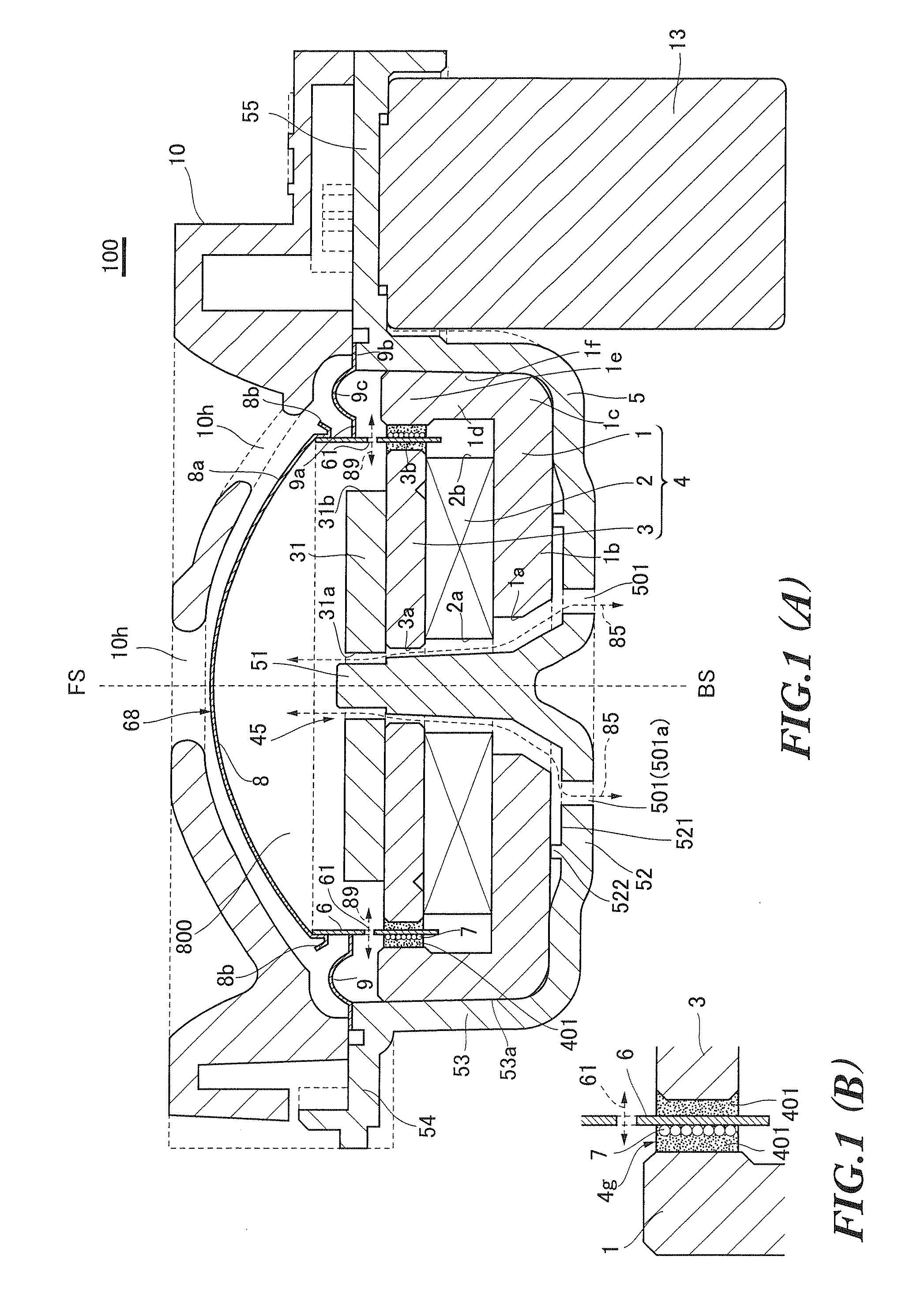
[0039]FIGS. 1(A), 1(B) are diagrams for illustrating a speaker device 100 according to a first embodiment of the present invention. Specifically, FIG. 1(A) is a sectional view for illustrating the speaker device according to the first embodiment of the present invention, and FIG. 1(B) is a diagrams for illustrating a magnetic fluid 401 placed in a magnetic gap 4g.

[0040]As illustrated in FIGS. 1(A) and 1(B), the speaker device 100 according to an embodiment of the present invention has a magnetic circuit 4 comprising a yoke 1, a magnet 2 and a plate 3, a frame (speaker frame) 5, a voice-coil bobbin 6, a voice coil 7, a diaphragm 8, an edge 9 and an equalizer 10.

[0041]The yoke 1 corresponds to an embodiment of a yoke according to the present invention, and the magnet 2 corresponds to an embodiment of a magnet according to the present invention. The plate 3 corresponds to an embodiment of a plate according to the present invention, and the magnetic circuit 4 corresponds to an embodime...

second embodiment

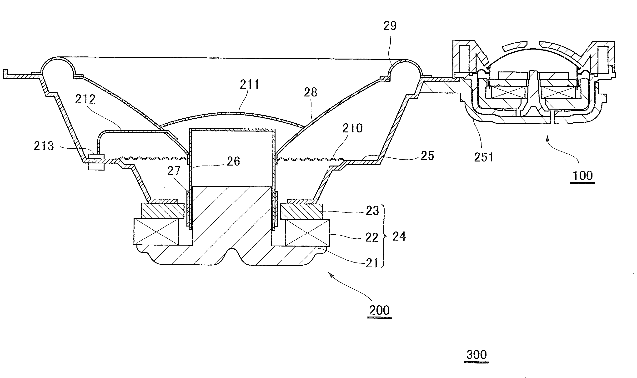
[0102]FIG. 7 is a sectional view illustrating a speaker unit 300 according to a second embodiment of the present invention. FIG. 8 is an enlarged sectional view of an area of the speaker unit 300 shown in FIG. 7 around a tweeter (speaker device 100). FIG. 9 is a rear view of the speaker unit 300 shown in FIG. 7. FIGS. 10(A), 10(B) are views illustrating a bracket 251 of the speaker unit 300 shown in FIG. 7. Specifically, FIG. 10(A) is a sectional view of the bracket 251 of the speaker unit 300 shown in FIG. 7. FIG. 10(B) is an enlarged view of an area of the bracket 251 shown in FIG. 10(A) around an air vent 2501.

[0103]As shown in FIG. 7 to FIGS. 10(A), 10(B), the speaker unit 300 according to the present embodiment has a main speaker device 200 and a tweeter (speaker device 100 for high frequency range).

[0104]The speaker unit 300 corresponds to an embodiment of a speaker unit according to the present invention, and the tweeter (speaker device 100 for high frequency range) correspon...

third embodiment

[0127]FIG. 11 is a sectional view of a speaker device 100B according to a third embodiment of the present invention. A description is omitted of the structure and functions common to the speaker device 100B according to the present embodiment and the speaker device 100 according to the first embodiment.

[0128]In contrast to the speaker device 100 according to the first embodiment, the speaker device 100B according to the present embodiment is not provided with a mounting portion 55 on which an electron device such as a capacitor is mounted. Apart from this point, the speaker device 100B is similar in structure to the speaker device 100. That is, when the speaker device 100 is not used as a tweeter of the speaker unit 300, the mounting portion 55 may not be provided as in the speaker device 100B shown in FIG. 11.


PUM


Abstract

A simple structure will achieve dissipation of heat from the area inside a voice-coil bobbin and a diaphragm without a reduction in sound quality, in which a process for assembling a speaker device with high accuracy is performed in a simple operation. A speaker device comprises a recess-shaped frame 5 which supports, through an edge 9, a vibration system member 68 provided with a diaphragm 8 coupled to a voice-coil bobbin 6, and a magnetic circuit 4 which comprises an approximately ring-shaped magnet 2 and an approximately ring-shaped plate 3 which are mounted on a yoke 1 disposed in the frame 5, and a magnet gap 4g in which a voice coil 7 wound on a voice-coil bobbin 6 is disposed. In the magnetic circuit 4 a through hole 45 extending in the vibration direction of the diaphragm is fitted over a center boss 51 of a shape protruding from the bottom of the frame 5 in the direction of the sound emission, so that the magnetic circuit 4 is positioned and fixed with respect to the frame 5. An air passage 85 is formed along the center boss 51 fitted into the through hole 45 of the magnetic circuit 4 to establish communication between the inside of the voice-coil bobbin 6 and the outside of the frame.

Description

TECHNICAL FIELD[0001]This invention relates to a speaker device and a speaker unit.BACKGROUND ART[0002]A typical speaker, for example, comprising a dome diaphragm has a voice coil wound on a voice coil bobbin connected to the diaphragm. The voice coil is disposed in a magnetic gap of a magnetic circuit so as to vibrate therein, and the diaphragm is fixed to a speaker frame through an edge. In the speaker structured as described above, upon receipt of an electric signal at the voice coil from the outside, the electromagnetic action produces a drive force on the voice coil, so that the diaphragm vibrates to emit a sound wave.[0003]In the speaker with the above structure, the space inside the voice coil and the diaphragm is substantially hermetically sealed. Because of this, disadvantageous problems may arise: during the operation of the speaker, the vibration of the diaphragm causes an air temperature in the sealed space to become relatively high; the heat generated on the voice coil ...

Claims


Application Information

Patent Timeline
IPC IPC(8): H04R1/00
CPCH04R1/24H04R9/022H04R2499/13H04R9/046H04R9/06H04R9/027
Inventor ENDO, NOBUHIRO
Owner PIONEER CORP
Why Eureka
Try Eureka