Rendering a mask using coarse mask representation

a mask and representation technology, applied in the field of integrated circuit (ic) fabrication, can solve the problems of inability to accurately represent polygons in bed of nails, inability to reduce output grid density, and inability to achieve the effect of reducing the density of output grids

Active Publication Date: 2009-07-16
SIEMENS PROD LIFECYCLE MANAGEMENT SOFTWARE INC
View PDF10 Cites 18 Cited by
  • Summary
  • Abstract
  • Description
  • Claims
  • Application Information

AI Technical Summary

Problems solved by technology

The above limitation applies both to reducing the density of the output grid and to situations where the density of the input grid needs to be increased.
This bed-of-nails representation of polygons would not be particularly accurate (at reasonable sampling densities) if used in isolation.
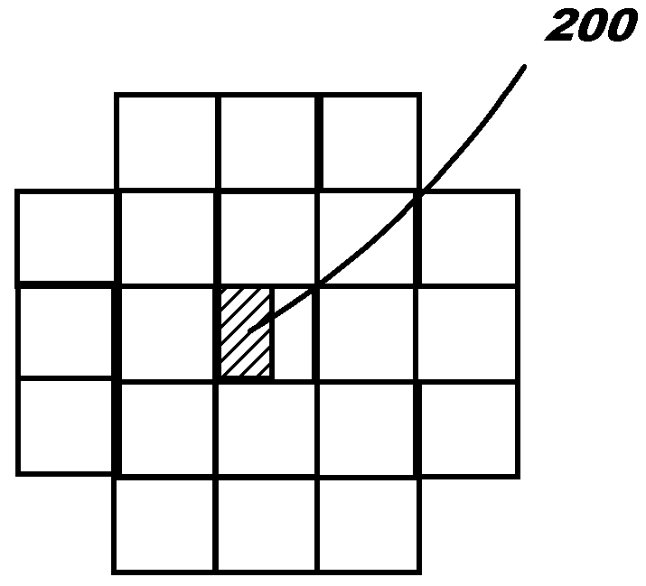
However, it is required that the size of the Manhattan mask polygon across each of its horizontal and vertical dimensions must be an integer multiple of the FFT grid step size for this method to work, which as discussed further herein, will usually not be the case.
It is no longer entirely adequate to neglect mask topography in the state-of-the-art lithography, where EMF effects represent a perturbation on ideal thin-mask behavior that is small but often non-negligible.
Unfortunately, the high density of the design gridding used in almost all IC masks poses a computational difficulty for the pixel-based simulation approaches.
It is the precision at which edges are positioned on the mask that poses a significant difficulty for pixel-based imaging.
It is completely impractical to calculate the SOCS image on a grid as fine as the design grid, which is of the order of 50 times finer than the Nyquist grid along each axis in a typical case.
As a result, the calculated images are inaccurate.
Error propagation then causes an increased error in the predicted position of the printed edge.
Even when this error is within the overall tolerance level allowed for prediction errors, it can still be of concern in an OPC.
This will cause the overhang conditions at a polygonal feature's edges to vary from instance to instance, resulting in variations in rendering errors.
As a consequence, invalid variations may exist in the OPCs assigned to different occurrences of the feature.
Since a calculation on the very fine design grid is completely impractical, present approaches instead attempt to make the rendered mask resemble the true mask as closely as possible.
This reduces the error that results from ignoring structure on the design-grid level, though it does not eliminate the error.
A difficulty of this conventional method is that the region where the rendered mask departs from the true mask is sharply bounded by the subpixel boundaries.
This sharp bounding of each gray-level region results in the generation of spurious high frequencies.
These high frequencies turn out to cause errors even though they are mostly outside the collection band of the projection lens.
Errors arise because the Fourier transform of a mask rendering that has been gridded at the sub-Nyquist sampling rate is mathematically equivalent to a convolution of the true diffracted spectrum with a broadly spaced comb function, thereby superimposing periodic repeats of the spatial frequency spectrum (diffraction pattern).
High frequencies in the sampling grid can interfere with (i.e., couple to) high frequencies in the diffraction pattern of the true mask, which produces low frequency artifacts (errors) that are collected by the lens.
However, gridding at the subsampling / sub-Nyquist rate does not eliminate these artifacts since the very high subsampling needed to fully match the high frequency design grid is impractical.
Note that while 4× subsampling achieves an accuracy that is only marginally accurate even in combination with transmission-matching of subpixels, it nonetheless entails a significant penalty in computation time.
As such, high frequency suppression (used for treating interfering high frequency) will be incomplete because the density-matching takes place within a spatially bounded subpixel.
In addition, complete suppression requires that the rendition extends across the full mask block under consideration (e.g., of size 10242 before subsampling), or at least across a block of subpixels that is significantly larger than the lens resolution, which would entail significant computational overhead, since many neighboring subpixels would need to be adjusted to render the overlapping subpixels.
Unfortunately, the Fourier transforms used in dense imaging might still require a much more substantial memory access overhead, since the Fourier transforms used in dense imaging would typically involve between, e.g., 1282 to 10242 orders, depending on the block size chosen, and most of these would fall within the circular support of the imaging kernels in the case where the pupil fill σ approaches 1.
In sum, while the present methods of rendering a mask make a reasonably balanced compromise between accuracy and speed, the final result is only marginally acceptable by either criterion.

Method used


Image

  • Rendering a mask using coarse mask representation
  • Rendering a mask using coarse mask representation
  • Rendering a mask using coarse mask representation

Examples


Embodiment Construction

[0040]The description includes the following headings for illustrative purposes only: I. Introduction and Definitions, II. System Overview, III. Operational Methodology, and IV. Conclusion.

I. INTRODUCTION AND DEFINITIONS

[0041]The current disclosure is based on, among others, an understanding that an image produced by a projection lens may be affected by the impulse response of the projection lens and the mutual coherence function of the illumination. It can be achieved that a simulated image of the mask matches an actual image produced by the projection lens without modeling the mask by representing the fine-structure of the mask. Specifically, rather than attempting to reproduce the fine-structure of a mask as accurately as possible in a simulation, the current disclosure constructs a coarse representation of the mask that has approximately the same Fourier transforms (FT) as the mask if both are bandlimited by the impulse response of a pseudo lens with a numerical aperture larger ...


PUM


Abstract

A method, system and computer program product for rendering a mask are disclosed. A method of rendering a mask may comprise: providing an initial mask design for a photolithographic process, the initial mask design including polygons; initially rendering the initial mask design as a coarse mask representation in a pixel based image calculation; identifying an overhang portion; and rendering the overhang portion using a set of subpixels whose artifacts from spatial-localization lie outside a practical resolution of a pseudo lens having a numerical aperture larger than that of a projection lens used in the photolithographic process; and updating the initial rendering based on the overhang portion rendering.

Description

BACKGROUND OF THE DISCLOSURE[0001]1. Technical Field[0002]The disclosure relates generally to an integrated circuit (IC) fabrication, and more particularly to rendering a mask as a coarse mask representation.[0003]2. Background Art[0004]Considerable efforts have been made in the field of photolithography to develop and implement methods of mask compensation and verification. For example, one approach implements optical proximity corrections (OPC) based on pixel-based simulations (also known as dense-image simulations). A key aspect of this simulation approach is that the images of the projected mask patterns are calculated on a regular grid, rather than at a sparse set of isolated adjustment (or characterization) points. The regularity of pixel-based imaging enables fast Fourier transform (FFT) based computations (e.g. convolutions). FFT-based convolutions are relatively rapid compared to the classic convolution algorithms used in the earlier sparsely sampled mode of OPC, assuming t...

Claims


Application Information

Patent Timeline
Patent Type & Authority Applications(United States)
IPC IPC(8): G06K9/36
CPCG03F1/144G03F7/705G03F1/36
Inventor LAVIN, MARK A.MUKHERJEE, MAHARAJROSENBLUTH, ALAN E.
Owner SIEMENS PROD LIFECYCLE MANAGEMENT SOFTWARE INC
Why Eureka
Try Eureka