
Electrode, lithium battery, method of manufacturing electrode, and composition for coating electrode

a technology of lithium battery and electrode, applied in the direction of electrode manufacturing process, electrochemical generator, cell component, etc., can solve the problems of conductive binder, difficult to improve both the conductivity and the binding strength of active material layer, and the conductive material can be electrically disconnected

Active Publication Date: 2009-07-16
SAMSUNG ELECTRONICS CO LTD
View PDF11 Cites 49 Cited by
  • Summary
  • Abstract
  • Description
  • Claims
  • Application Information

AI Technical Summary

Benefits of technology

[0012]Additional aspects and / or advantages of the invention will be set forth in part in the description which follows and, in part, will be obvious from the description, or may be learned by practice of the invention.

Problems solved by technology

Although the conductive material improves the charging and discharging characteristics of the secondary cell, since the conductive material is not adhesive, the conductive material can be electrically disconnected, due to cracks generated during charging and discharging operations of the secondary cell.
Although the binder is useful for preventing cracks, the binder is not conductive.
Therefore, both the conductive material and the binder need to be included in the active material layer, and thus, it is difficult to improve both the conductivity and the binding strength of the active material layer.

Method used


Image

  • Electrode, lithium battery, method of manufacturing electrode, and composition for coating electrode
  • Electrode, lithium battery, method of manufacturing electrode, and composition for coating electrode
  • Electrode, lithium battery, method of manufacturing electrode, and composition for coating electrode

Examples


fabrication example 1

Preparation of electrode ink

[0059]58.3 g of water, 5.7 g of ethanol, 30.9 g of ethylene glycol, 1.9 g of diethylene glycol, 0.38 of triethanol amine, 1.52 g of LiFePO4, 0.19 g of dispersant (Ciba, Switzerland, EFKA4580), and 0.05 g of carboxymethyl cellulose (CMC) were mixed to form a mixture. The mixture was passed through a membrane syringe filter having a pore size of about 5 μm. In this way, an electrode ink (active material composition) was prepared.

example 1

Preparation of Dispersion

[0060]15 mg of CMC was dissolved in 30 ml of distilled water, and 30 mg of multi-wall carbon nanotubes (ILJIN nanotech, Korean, CM-95) were added to the mixture. Thereafter, the resulting mixture was treated using ultrasonic waves, to disperse the CMC and the carbon nanotubes. Then, the mixture was centrifuged at 10000 rpm, for 10 minutes, to remove precipitates and to obtain a dispersion, in which the carbon nanotubes and the CMC were dispersed.

example 2

Fabrication of Electrode

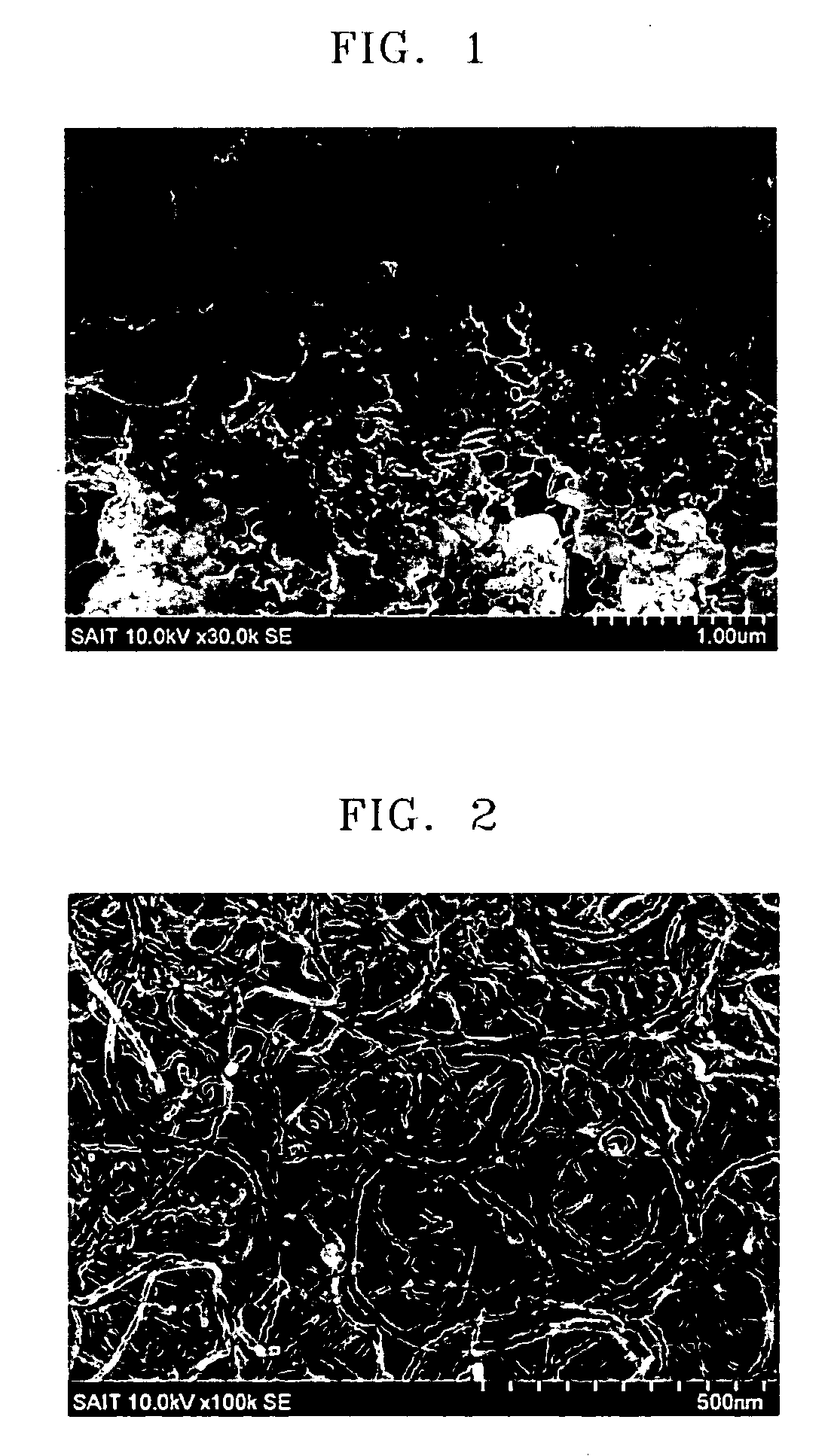
[0061]The dispersion of Example 1 was sprayed (coated) onto an aluminum current collector, using a spraying device (NVD-600, Fujimori Technology Laboratory Inc.). Spraying conditions were as follows: substrate temperature 70° C.; nozzle speed 600 mm / sec; nozzle-to-substrate distance 10 cm; spraying pitch 10 mm; spraying range 15 cm×15 cm; and injection rate 1 ml / min. The spraying of the dispersion was performed 15 times. A coating layer including a structural network was formed through the spraying of the dispersion. An electron micrograph of the structural network is illustrated in FIG. 2.

[0062]Thereafter, the aluminum current collector coated with the dispersion was cut into 10 cm×8 cm rectangle and then was attached to a poly ethylene telephthalate (PET) film. Then, an 8 cm×6 cm pattern was printed on the cut aluminum current collector, using the electrode ink of Fabrication example 1. For this, an HP Deskjet 5550 was used.

[0063]Next, the aluminum current ...


PUM


Abstract

An electrode including a current collector, and an active material layer disposed on the current collector. The active material layer includes a structural network and an active material composition. The structural network includes a network of carbon nanotubes and a binder. The active material composition includes an active material and a polar medium.

Description

CROSS-REFERENCE TO RELATED PATENT APPLICATION[0001]This application claims the benefit of Korean Patent Application No. 2008-4590, filed on Jan. 15, 2008, in the Korean Intellectual Property Office, the disclosure of which is incorporated herein in its entirety by reference.BACKGROUND OF THE INVENTION[0002]1. Field of the Invention[0003]Aspects of the present invention relate to an electrode, a lithium battery including the electrode, a method of manufacturing the electrode, and a composition for coating the electrode.[0004]2. Description of the Related Art[0005]Electrodes of a secondary cell include a metal current collector and an active material layer formed on the metal current collector. The active material layer includes an active material, a conductive material, a binder, and / or a surfactant. The conductive material is used for increasing the conductivity of the active material layer and for increasing the interfacial conductivity between the metal current collector and the a...

Claims


Application Information

Patent Timeline
IPC IPC(8): H01M4/62B05D5/12B82Y99/00H01M4/02H01M4/04H01M4/06H01M4/08H01M4/13H01M4/139H01M4/66H01M4/96
CPCB82Y30/00H01M4/13H01M4/1393H01M4/366H01M4/5825Y02E60/122H01M4/625H01M4/667H01M6/40H01M10/0525H01M10/0585H01M4/622H01M4/0419H01M4/139H01M10/052H01M2004/021Y02E60/10H01M4/133
Inventor KWON, MOON-SEOKYOON, SEON-MICHOI, JAE-MANKIM, HAN-SUSHIN, HYEON-JINCHOI, JAE-VOUNG
Owner SAMSUNG ELECTRONICS CO LTD
Learn More