Flexible planar heating device

a heating device and flexible technology, applied in resistors, ohmic resistance heating, electrical devices, etc., can solve the problems of sacrificing heating time, heat is not evenly distributed, and the heating device cannot be folded or bended, so as to reduce electricity consumption and achieve uniform heating

Inactive Publication Date: 2009-07-23
TOP BOUND ENTERPRISE
View PDF10 Cites 9 Cited by
  • Summary
  • Abstract
  • Description
  • Claims
  • Application Information

AI Technical Summary

Benefits of technology

[0006]Accordingly, a novel flexible planar heating device is provided herein that avoids the use of point contact

Problems solved by technology

The common drawbacks of these heating devices are that it takes a considerable amount of time for the heat-producing member to heat up, the heat is not evenly distributed, and the heating devices usually cannot be folded or bended.
A high temperature is usually developed at these contact points, which would cause some protective covers to the heating device to catch fire and, therefore, presents a potential hazard to the user.
Additionally, these protective covers could be easily peeled off after a period of usage and the heating device is therefore not properly insulated.
For example,

Method used


Image

  • Flexible planar heating device
  • Flexible planar heating device
  • Flexible planar heating device

Examples


Embodiment Construction

[0022]The following descriptions are exemplary embodiments only, and are not intended to limit the scope, applicability or configuration of the invention in any way. Rather, the following description provides a convenient illustration for implementing exemplary embodiments of the invention. Various changes to the described embodiments may be made in the function and arrangement of the elements described without departing from the scope of the invention as set forth in the appended claims.

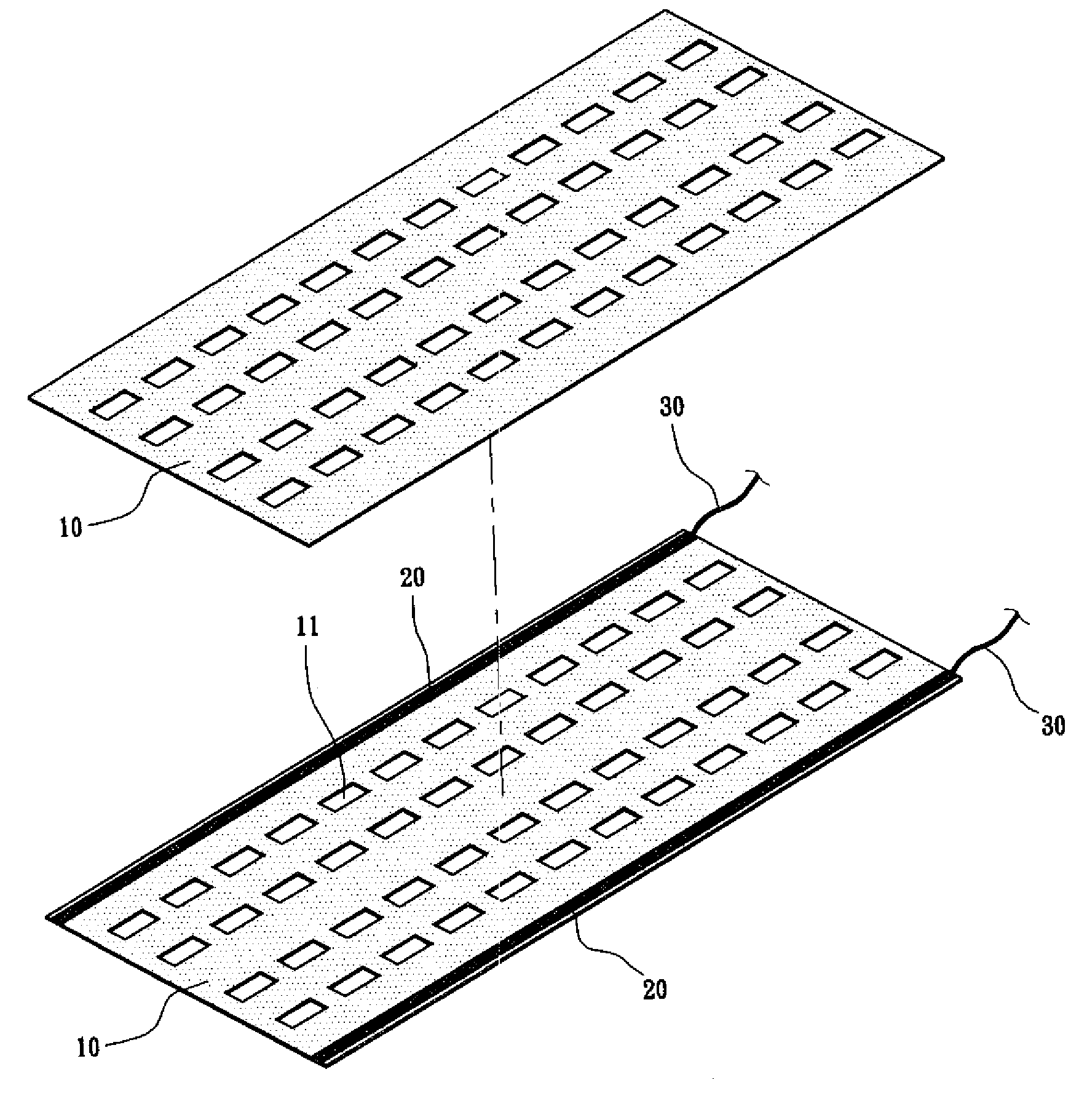
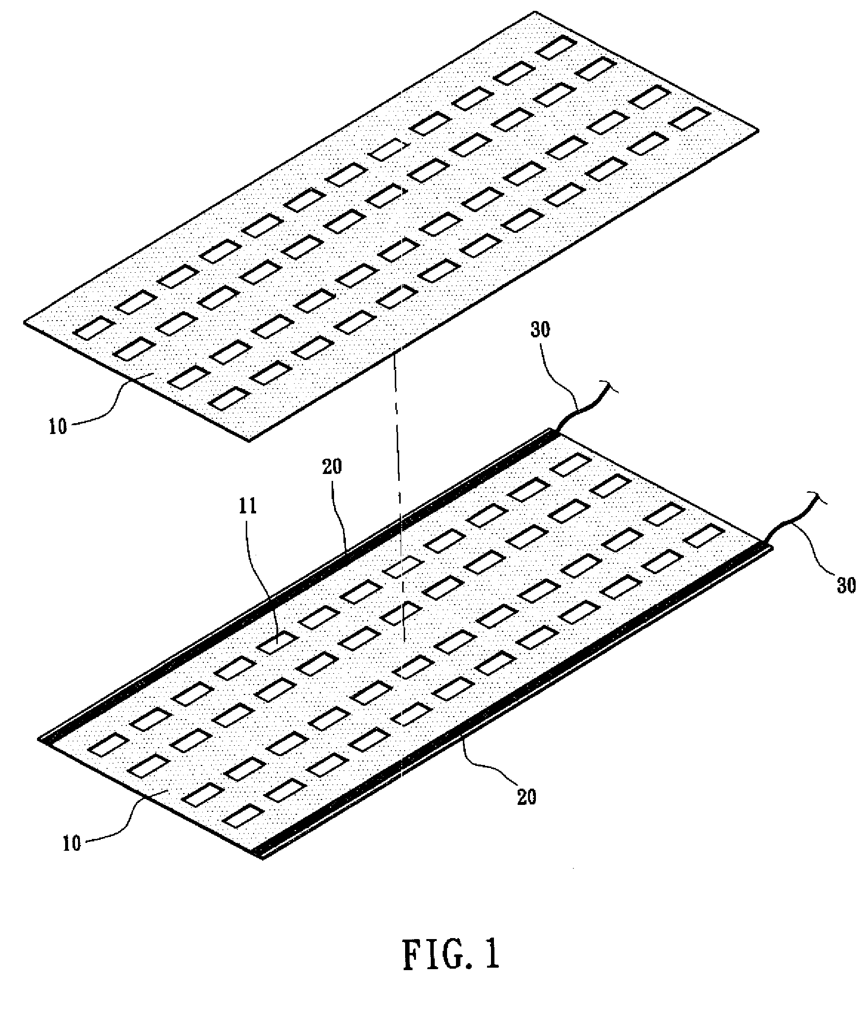
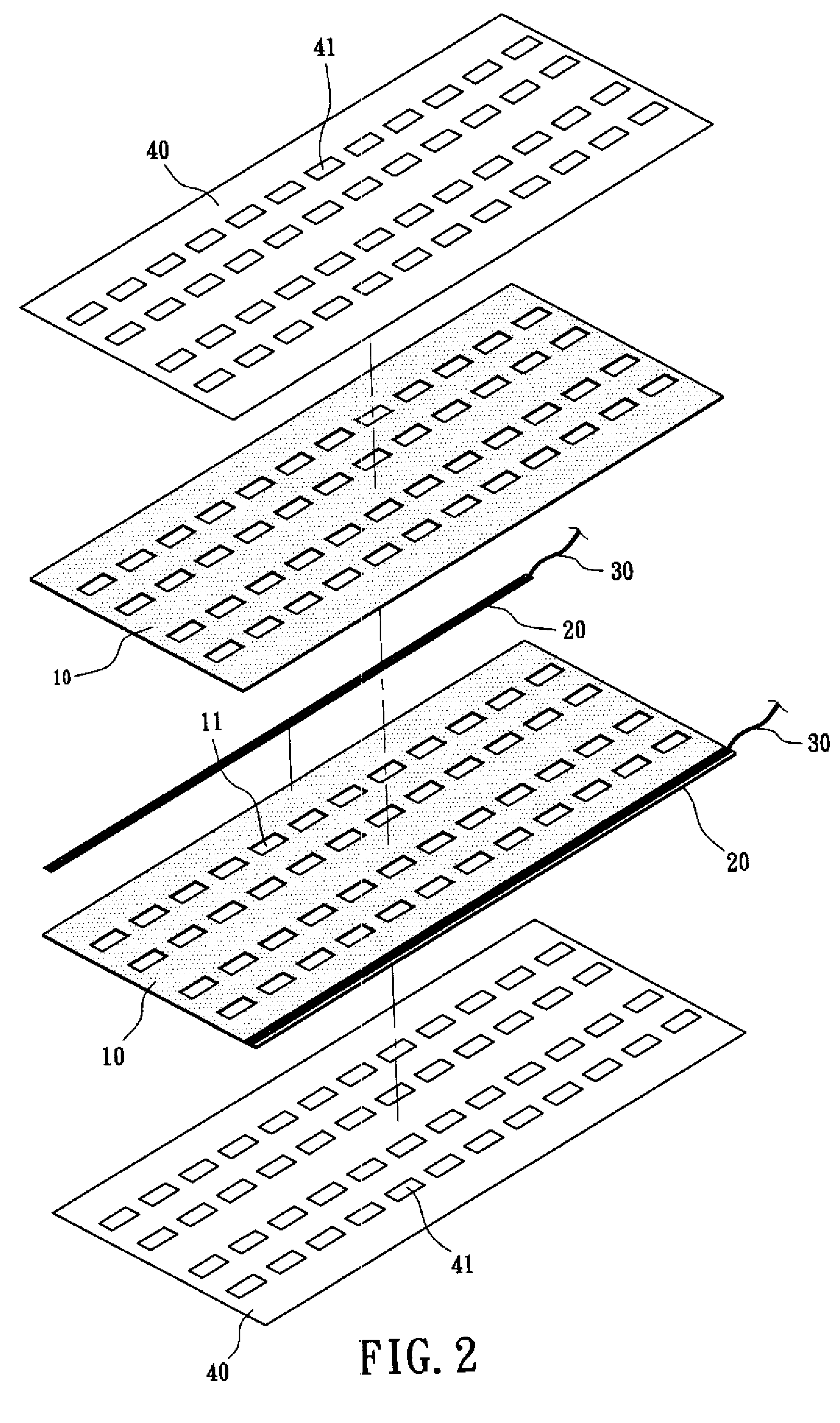
[0023]As shown in FIGS. 1 and 2, a planar heating device according to an embodiment of the present invention contains two flat first conducting members 10 capable of conducting electricity and producing heat, a number of flat and elongated second conducting members 20 capable of conducting electricity with low resistance sandwiched between the first conducting members 10, a number of conducting wires 30 each having at least an end connected to a second conducting member 20, two flat insulating membe...


PUM


Abstract

A heating device which includes two first conducting members and at least a second conducting member, wherein the first conducting members are made of silicone rubber conductor and flexibly pressed into an upper thin layer and a lower thin layer between which is arranged the second conducting member. The first and second conducting members are formed into a whole unit by heat and pressure, which are provided holes at predetermined positions for increasing the contact area to disperse electrical current and conducting wires for connection in parallel or series with the power source. Voltages from 0.1V˜500V AC or DC are all applicable. Hence, the first and second conducting members can dissipate heat evenly. The increased temperature ranges from 1˜230° C. with respect to the environmental temperature thereby preventing the formation of high temperature points. Furthermore, the holes can reduced the electrical current required.

Description

(a) TECHNICAL FIELD OF THE INVENTION[0001]The present invention generally relates to heating devices, and more particularly to a flexible planar heating device whose heat producing members connect to a power source via a number of low-resistance members.(b) DESCRIPTION OF THE PRIOR ART[0002]In conventional planar heating devices, conducting wires or rigid circuit boards are arranged across a planar heat-producing member so as to create a large warm area. The common drawbacks of these heating devices are that it takes a considerable amount of time for the heat-producing member to heat up, the heat is not evenly distributed, and the heating devices usually cannot be folded or bended.[0003]Flexible planar heating devices using various types of fabrics as heat-producing members are disclosed, for example, in R.O.C. Taiwan Patent Nos. M257591 and M294805. These devices have their power cables connected to the heat-producing members via point contacts such as those by soldering or rivetin...

Claims


Application Information

Patent Timeline
IPC IPC(8): H05B3/34H01C3/06
CPCH01C3/06H05B3/34H05B2203/005H05B2203/036H05B2203/011H05B2203/013H05B2203/017H05B2203/01
Inventor WU, KUEI-HUANG
Owner TOP BOUND ENTERPRISE
Why Eureka
Try Eureka