
Mode-matching system for tunable external cavity laser

a laser and mode matching technology, applied in the direction of laser details, laser optical resonator construction, semiconductor lasers, etc., can solve the problems of limiting the frequency range that still safely, the frequency output is especially unstable, and the diffraction grating has limited the diffraction range available, so as to achieve the effect of improving spectral purity

Inactive Publication Date: 2009-07-23
FARMIGA NESTOR O +2
View PDF14 Cites 3 Cited by
  • Summary
  • Abstract
  • Description
  • Claims
  • Application Information

AI Technical Summary

Benefits of technology

This approach enables expanded frequency tuning ranges with improved spectral purity and stability, effectively compensating for environmental influences and maintaining coherent output over a broader frequency range.

Problems solved by technology

The frequencies available for diffraction by the diffraction grating are limited to those that are amplified and emitted from the lasing cavity.
Frequency outputs are especially unstable within the regions of transition, where mode hops and multiple lasing frequencies are observed.
Temperature variations and other disturbances can shift the mode frequencies further, limiting the frequency ranges that still safely avoid the regions of transition.

Method used


Image

  • Mode-matching system for tunable external cavity laser
  • Mode-matching system for tunable external cavity laser
  • Mode-matching system for tunable external cavity laser

Examples


Embodiment Construction

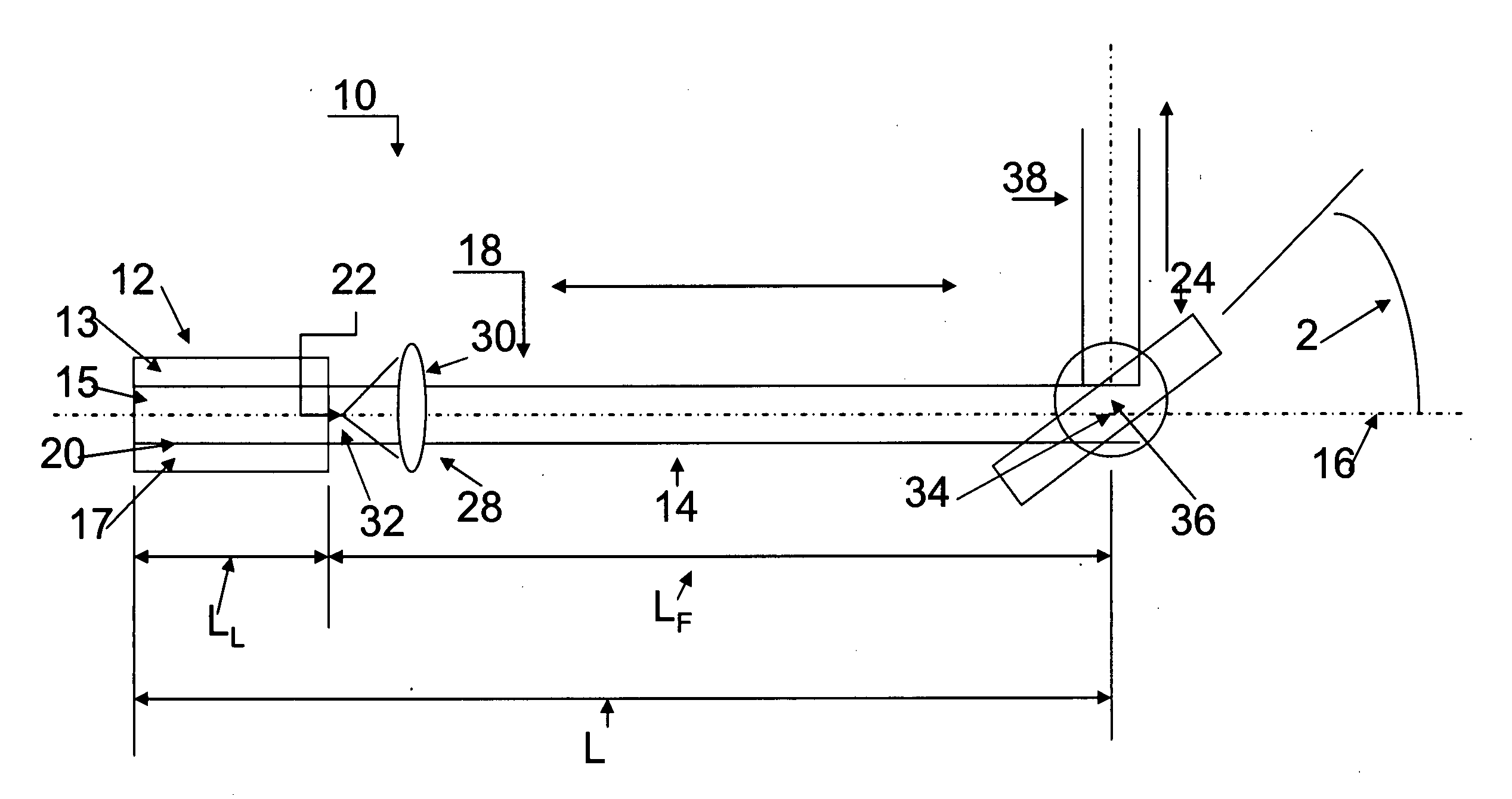
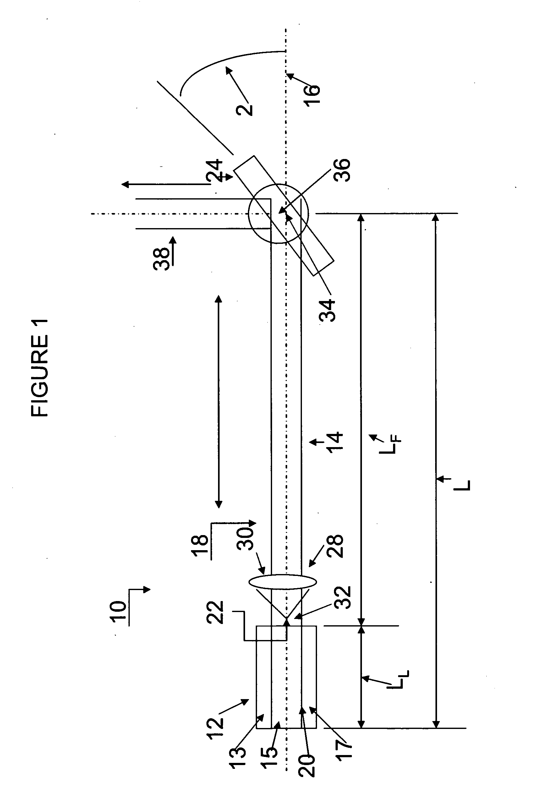
[0031]As shown in FIG. 1 a laser 10, which is preferably a semiconductor diode laser, includes a lasing cavity 12 and an adjoining feedback cavity 14 aligned along a common optical axis 16. Together, the cavities 12 and 14 form an external cavity 18.

[0032]The lasing cavity 12 contains a lasing medium (an active layer) 15 sandwiched between two electrically biased regions 13 and 17 (e.g., p and n regions) and has a fixed length along the optical axis 16 between a reflective back surface 20 and a reflective front surface 22 located at opposite ends of the lasing cavity 12. The gain is such for conventional laser diodes that the front surface 22 requires only a small reflectivity (e.g., approximately 4 percent) to support resonant frequency modes. The feedback cavity 14, which is filled with air, has a fixed length between the front surface 22 of the lasing cavity 12 and a pivotable reflective surface 24 located at an opposite end of the feedback cavity 14. A collimating lens 28 forms ...


PUM


Abstract

An external cavity laser includes a lasing cavity and an optically coupled feedback cavity having differently spaced resonant lasing and feedback mode frequencies. The lasing modes can be collectively or individually matched to selected feedback modes. For example, a current driving the lasing cavity can be adjusted to shift individual lasing modes into alignment with the selected feedback modes.

Description

FIELD OF INVENTION[0001]Tunable external cavity lasers include a lasing cavity having resonant modes for amplifying a range of beam frequencies and a feedback cavity optically coupled to the lasing cavity and having resonant modes subject to selection for tuning the beam frequency output of the lasers.DESCRIPTION OF RELATED ART[0002]Light resonates within laser cavities between front and back surfaces in distinct frequency modes at which standing waves are produced by complete round trips taken by integer numbers of wavelengths between the surfaces. The potential for gain within the laser cavities varies as a distribution function of frequency, and the optical power tends to concentrate in the frequency mode experiencing the highest gain or, conversely, the lowest loss. Beyond encounters with a lasing medium within the laser cavities, most other encounters of the light within the laser cavities entail losses, and the mode frequency experiencing the lowest loss is generally the one m...

Claims


Application Information

Patent Timeline
Patent Type & Authority Applications(United States)
IPC IPC(8): H01S3/098
CPCH01S3/08036H01S5/141H01S5/14H01S5/065
Inventor FARMIGA, NESTOR OLITZENERGET, MICHAEL JOSEPHTRONOLONE, MARK JOSEPH
Owner FARMIGA NESTOR O
Learn More