Dry film protoresist for a micro-fluid ejection head and method therefor

a technology of microfluid ejection and protoresist, which is applied in the field of microfluid ejection head, can solve the problems of low yield of acceptable microfluid ejection head structure, and achieve the effect of uniform thickness and improved planarity of the coated layer

Inactive Publication Date: 2009-07-23
LEXMARK INT INC
View PDF8 Cites 28 Cited by
  • Summary
  • Abstract
  • Description
  • Claims
  • Application Information

AI Technical Summary

Benefits of technology

[0002]Micro-fluid ejection heads are useful for ejecting a variety of fluids including inks, cooling fluids, pharmaceuticals, lubricants and the like. A widely used micro-fluid ejection head is in an ink jet printer. Ink jet printers continue to be improved as the technology for making the micro-fluid ejection heads continues to advance. New techniques are constantly being developed to provide low cost, highly reliable printers which approach the speed and quality of laser printers. An added benefit of ink jet printers is that color images can be produced at a fraction of the cost of laser printers with as good or better quality than laser printers. All of the foregoing benefits exhibited by ink jet printers have also increased the competitiveness of suppliers to provide comparable printers in a more cost efficient manner than their competitors.
[0003]One area of improvement in the printers is in the print engine or micro-fluid ejection head itself. This seemingly simple device is a relatively complicated structure containing electrical circuits, ink passageways and a variety of tiny parts assembled with precision to provide a powerful, yet versatile micro-fluid ejection head. The components of the ejection head must cooperate with each other and with a variety of fluid formulations to provide the desired ejected fluid properties. Accordingly, it is important to match the ejection head components to the fluid and the duty cycle demanded by the ejection device. Slight variations in production quality can have a tremendous influence on the product yield and resulting fluid ejector performance.
[0005]An advantage of a dry film lamination method for constructing micro-fluid ejection heads is that wafer level processing of multiple ejection heads may be conducted simultaneously rather than assembling individual components to individual ejection head substrates. The material to be laminated to the thick film layer on a substrate to provide the nozzle plate layer is produced in a separate process and then laminated with pressure and / or heat to the thick film layer. However, variations in the thickness, smoothness, and uniformity of the nozzle plate laminate material makes further processing of the nozzle plate difficult and may result in low yields of acceptable micro-fluid ejection head structures.
[0006]Accordingly, what are needed are an improved dry film photoresist laminate material and an improved process for making the dry film laminate material to provide more uniform nozzle plate layers.
[0009]An advantage of the embodiments described herein is that the dry film photoimageable layer used for the nozzle plate has an essentially uniform thickness and is substantially devoid of air bubbles, streaks, and / or grooves. An exposed surface of the photoimageable layer on the substrate structure may have a surface roughness (Ra) value of less than about 20 nanometers and a maximum peak to value (Rt) value of less than about 1 micron. Since the slot die coating method applies liquid under substantially constant pressure to a moving web from a closed pressure container, air entrapment in the liquid that may cause the air bubbles is avoided. Another advantage of the slot die coating method over conventional coating methods is that evaporation of liquid components of the photoimageable liquid material is minimized. Accordingly, an essentially consistent solids content of the photoimageable liquid material may be maintained during the coating process thereby enabling improved planarity of the coated layer.BRIEF DESCRIPTION OF THE DRAWINGS

Problems solved by technology

However, variations in the thickness, smoothness, and uniformity of the nozzle plate laminate material makes further processing of the nozzle plate difficult and may result in low yields of acceptable micro-fluid ejection head structures.

Method used


Image

  • Dry film protoresist for a micro-fluid ejection head and method therefor
  • Dry film protoresist for a micro-fluid ejection head and method therefor
  • Dry film protoresist for a micro-fluid ejection head and method therefor

Examples


Embodiment Construction

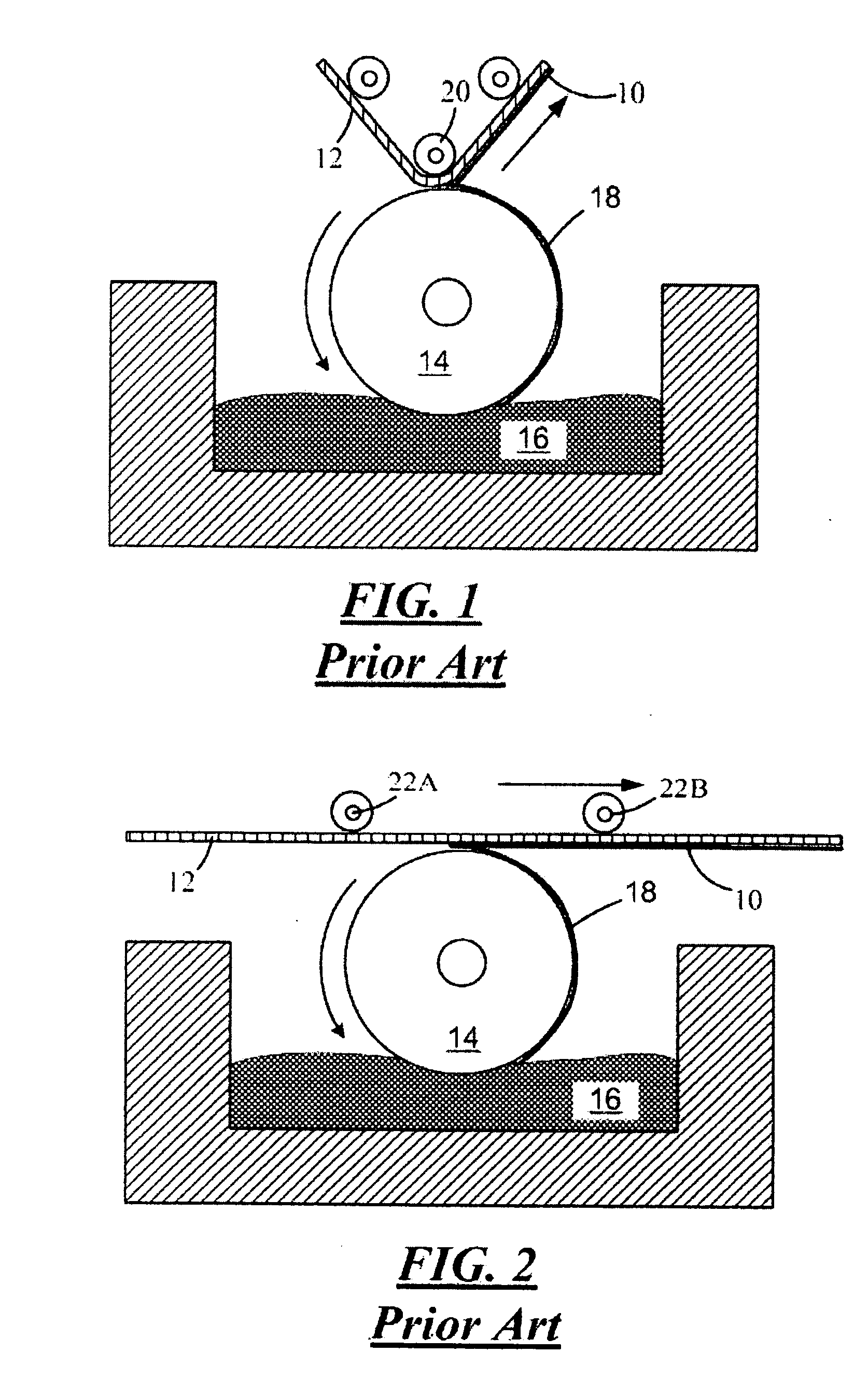
[0021]As set forth above, improved micro-fluid ejection heads may include nozzle members having a substantially uniform thickness that are substantially devoid of air bubbles, streaks, and / or grooves. Conventional processes used to provide dry film photoimageable layers include rotogravure techniques as illustrated in FIGS. 1 and 2. In a first prior art technique, a photoimageable layer 10 is applied to a moving web of backing material 12 using an elongate engraved roll 14 that rotates in a pool 16 of liquid photoresist material. As the roll 14 rotates, a thin film 18 of the photoresist material is captured in grooves on the roll and is applied to the moving web 12 that is kept in contact with the roll 14 by a back up roller 20. In FIG. 2, an off-roller gravure coating method is illustrated wherein two rollers 22A and 22B are offset from the roll 14 for maintaining the web 12 in contact with the grooved roll 14. In both FIGS. 1 and 2, the thin film 18 on the roll 14 is applied to th...


PUM

PropertyMeasurementUnit
thicknessaaaaaaaaaa
thicknessaaaaaaaaaa
thicknessaaaaaaaaaa

Abstract

A method for making a dry film photoresist layer for a micro-fluid ejection head and a micro-fluid ejection head made by the method. The method includes applying a photoimageable liquid to a moving web of release material to provide a photoimageable layer on the release material using a slot die coater. The layer on the release material has a coating thickness ranging from about 8 to about 25 microns with a thickness variation of no more than about one micron. The photoimageable layer on the web is dried to provide a dry film photoresist layer. A protective web is then applied to the dry film photoresist layer.

Description

TECHNICAL FIELD[0001]The disclosure relates to micro-fluid ejection heads, and in particular to improved dry film photoresist materials for laminating to a micro-fluid ejection head structure to provide a substantially planarized, relatively thin photoresist film on the structure.BACKGROUND AND SUMMARY[0002]Micro-fluid ejection heads are useful for ejecting a variety of fluids including inks, cooling fluids, pharmaceuticals, lubricants and the like. A widely used micro-fluid ejection head is in an ink jet printer. Ink jet printers continue to be improved as the technology for making the micro-fluid ejection heads continues to advance. New techniques are constantly being developed to provide low cost, highly reliable printers which approach the speed and quality of laser printers. An added benefit of ink jet printers is that color images can be produced at a fraction of the cost of laser printers with as good or better quality than laser printers. All of the foregoing benefits exhibi...

Claims


Application Information

Patent Timeline
Patent Type & Authority Applications(United States)
IPC IPC(8): G03F7/004G03F7/26
CPCB41J2/1603B41J2/1628B41J2/1629G03F7/161B41J2/1645G03F7/0035B41J2/1631
Inventor FANNIN, BRYAN THOMASGRAHAM, DAVID CHRISTOPHERWEAVER, SEAN TERRANCE
Owner LEXMARK INT INC
Why Eureka
Try Eureka