Physical Finite Element Model

a finite element model and physical finite element technology, applied in the field of aircraft instrumentation, can solve the problems of aircraft occasionally sustain damage, material fatigue can worsen, and repair team personnel often expend a considerable amount of time locating

Active Publication Date: 2009-07-30
THE BOEING CO
View PDF9 Cites 17 Cited by
  • Summary
  • Abstract
  • Description
  • Claims
  • Application Information

AI Technical Summary

Benefits of technology

[0005]In another implementation, an aircraft includes one or more structural elements. The aircraft further includes a plurality of radio frequency identification devices (RFIDs) supported at respective locations by the one or more structural elements. The plurality of RFIDs define respective nodes of a mesh. At least one of the RFIDs includes a memory and is configured to determine a designation and a location of at least one other RFID proximate thereto within the mesh by way of wireless signals. The at least one RFID is also configured to store the designation and the location of the at least one other RFID in the memory. The at least one RFID is further configured to transmit at least some information stored in the memory by way of wireless signals.

Problems solved by technology

Aircraft occasionally sustain damage that is overlooked.
In rare cases, stress and the resulting material fatigue can worsen.
Once damage is reported, repair team personnel often expend a considerable amount of time locating, retrieving and analyzing structural and design data for an aircraft.
Such retrieval and analysis can require many days or weeks, resulting in protracted “down time” for the aircraft.

Method used


Image

  • Physical Finite Element Model
  • Physical Finite Element Model
  • Physical Finite Element Model

Examples


Embodiment Construction

[0015]The present disclosure introduces systems and methods for implementing a damage and / or structural failure detection system within an aircraft or other entity. Many specific details of certain embodiments of the disclosure are set forth in the following description and in FIGS. 1-6 to provide a thorough understanding of such embodiments. One skilled in the art, however, will understand that the disclosure may have additional embodiments, or that the disclosure may be implemented without several of the details described in the following description.

[0016]Illustrative Operating Environment

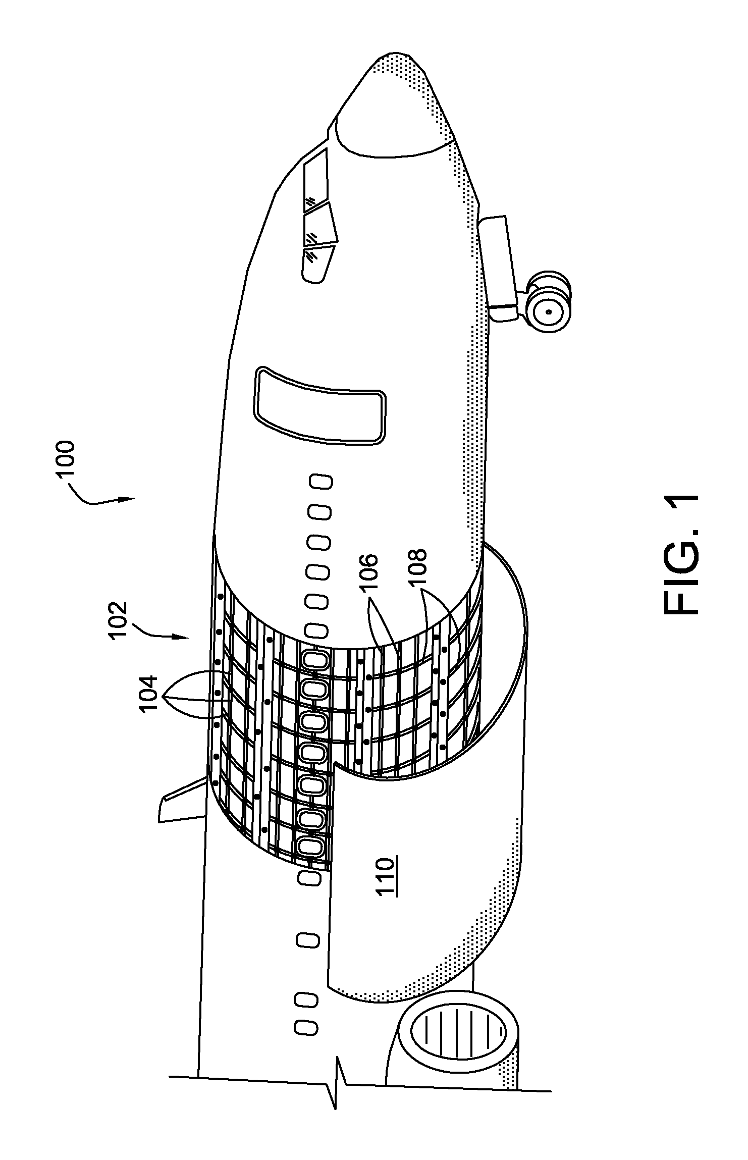
[0017]FIG. 1 is a partial cutaway view of an aircraft 100. The aircraft 100 is illustrative and non-limiting with respect to the present teachings. The aircraft 100 includes a structure 102 comprising a plurality of structural elements 104. The structural elements 104 collectively define a framework or “skeleton” for the aircraft 100. In particular, structural elements 104 that are oriented fore...


PUM


Abstract

a plurality of RFIDs is installed on aircraft or other structure. The RFIDs can query one another upon original installation and in response to predetermined event detection, and determine their relative locations within a mesh. The determined location data and other information are stored within the respect memories of the RFIDs. The stored data can be later accessed and used in analyzing damage or structural failure of the aircraft. Corrective measures are thus expedited because before-and-after structural comparisons can be readily made, with or without reference to original engineering data for the aircraft.

Description

FIELD OF THE DISCLOSURE[0001]The field of the present disclosure relates to aircraft instrumentation, and more specifically, to automatically detecting and reporting damage and related structural data for an aircraft by way of a mesh of radio frequency identification devices.BACKGROUND OF THE DISCLOSURE[0002]Aircraft occasionally sustain damage that is overlooked. In rare cases, stress and the resulting material fatigue can worsen. Once damage is reported, repair team personnel often expend a considerable amount of time locating, retrieving and analyzing structural and design data for an aircraft. Such retrieval and analysis can require many days or weeks, resulting in protracted “down time” for the aircraft. Additionally, analysis and determination of corrective measures requires that the necessary structural and design information be accessible in the first place. Therefore, improved damage detection and reporting, as a well as ready access to necessary data, would have great util...

Claims


Application Information

Patent Timeline
Patent Type & Authority Applications(United States)
IPC IPC(8): G08B21/00G08B13/14G01M99/00
CPCG01B15/06G01M5/0091G01M5/0083G01M5/0033G01B7/003G01B7/004G01B7/14G01B7/16G01B7/287G01M5/0016G01M5/0041G01M7/00G01M17/00
Inventor LINDGREN, LAWRENCE S.
Owner THE BOEING CO
Why Eureka
Try Eureka