
Waste liquid processing device

Inactive Publication Date: 2009-07-30
SEIKO EPSON CORP
View PDF12 Cites 6 Cited by
  • Summary
  • Abstract
  • Description
  • Claims
  • Application Information

AI Technical Summary

Benefits of technology

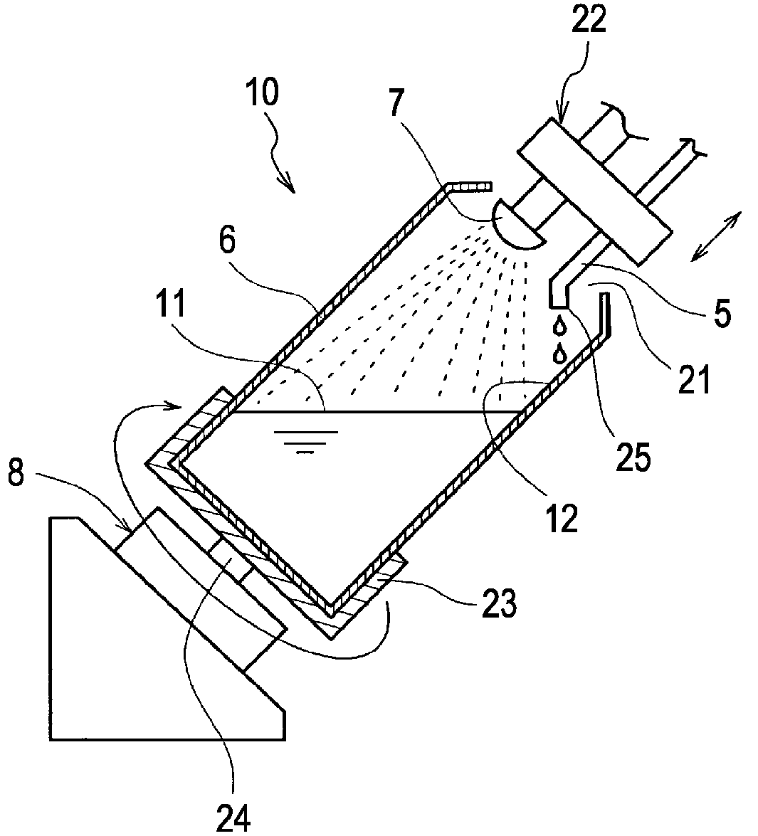
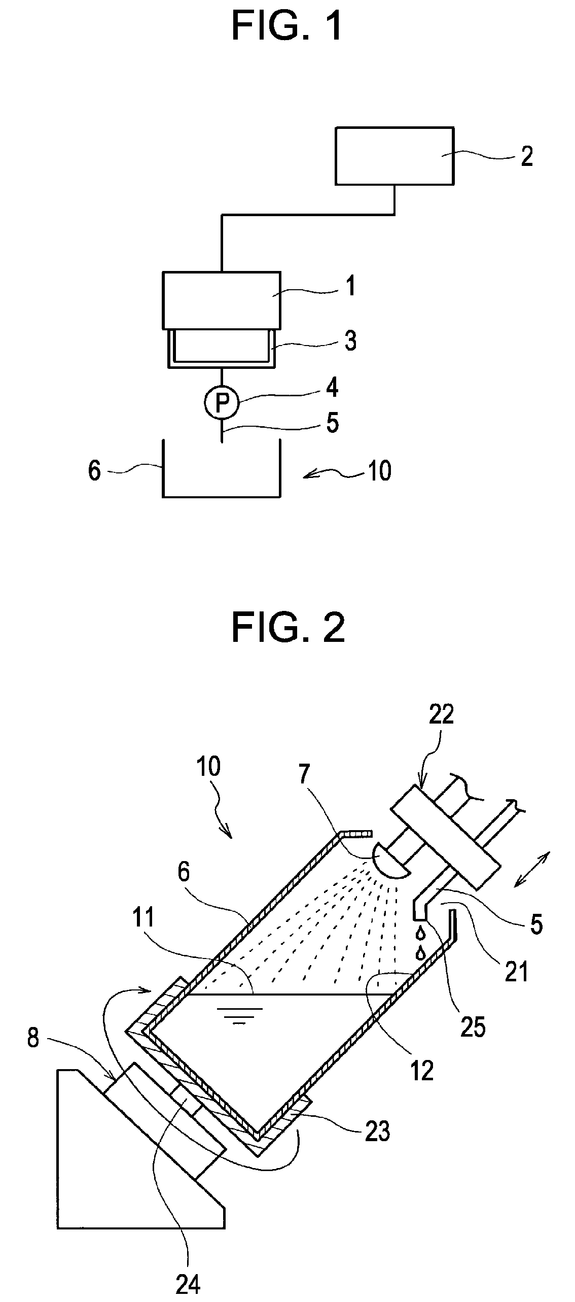
[0015]An advantage of some aspects of the invention is that it provides a waste liquid processing device capable of converting a liquid into a harmless solid with certainty, collecting the solid and stably and readily performing a waste liquid process.

Problems solved by technology

Since a recording head of the ink jet recording apparatus ejects an ink pressurized in a pressure generation chamber from nozzles on a recording sheet as ink droplets so as to perform printing, an ejection failure state is generated by the increase of ink viscosity due to the vaporization of a solvent from nozzle openings, the solidification of the ink, the attachment of dust, and the mixture of air bubbles.
Thus, a printing failure occurs.
However, in JP-A-2004-155047, since the absorber or the cured liquid is not necessarily transparent although the waste liquid container is transparent and the ultraviolet rays are irradiated in a state in which the waste ink is absorbed in the absorber, the ink is rapidly cured in a portion close to the outside of the transparent waste liquid container because the flow of the ultraviolet ray is excellent, but the ink is left in an uncured state at the inside of the waste liquid container because the ultraviolet rays are hard to reach the inside of the waste liquid container.
If the ultraviolet curable liquid includes many materials having skin irritation, has strong irritating odor, and is in an uncured state, the ultraviolet curable liquid has a bad influence on the human body when directly being brought into contact with the skin of a person.
In addition, a working environment is bad due to irritating odor.
However, if the ultraviolet curable liquid is cured, the ultraviolet curable liquid becomes harmless and irritating odor is suppressed.
Accordingly, if the ultraviolet curable liquid is left in the uncured state like the apparatus of JP-A-2004-155047, the stability or the comfort of the working environment cannot be ensured when the waste liquid container is collected and an incineration treatment is performed.
If the liquid is cured in a state of being absorbed in the absorber, the next collected liquid is hard to be absorbed in the absorber and thus the waste liquid cannot be collected although a surplus capacity exists in the collection amount of the waste liquid container.
In this case, since a deviation occurs by the absorption state or the curing state of the waste liquid, the life span of the waste liquid tank is not constant and replacement timing cannot be adequately informed to a user.
Thus, the device is not enlarged and is compact.

Method used


Image

  • Waste liquid processing device
  • Waste liquid processing device
  • Waste liquid processing device

Examples


second embodiment

[0056]FIGS. 4A-4F are views showing a waste liquid tank 6 applied to a waste liquid processing device according to the invention.

first embodiment

[0057]FIG. 4A is a longitudinal cross-sectional view of the waste liquid tank 6 and FIG. 4B is a lateral cross-sectional view of the waste liquid tank 6 having the cylindrical shape, which is shown in the

[0058]As shown in FIGS. 4C to 4F, an agitating promoting portion for promoting agitating of a waste liquid, which occurs by rotation of the waste liquid tank 6, may be provided in the waste liquid tank 6.

[0059]In FIG. 4C, swelling portions 26 which swell from the circumferential wall of the waste liquid tank 6 toward the inside thereof are formed at plural places (four places, in this example). The swelling portions 26 are formed to extend in an axial direction, and promotes the motion of the liquid level, that is, the agitating of the waste liquid, which occurs by the rotation of the waste liquid tank 6, when the waste liquid tank 6 in which the waste liquid is contained rotates around the axis of the cylindrical shape. That is, in this example, the swelling portions 26 function as...

third embodiment

[0063]FIG. 5A shows a waste liquid processing device according to the invention. In this embodiment, the axis of a waste liquid tank 6 having a cylindrical shape is arranged along a vertical direction and the waste liquid tank 6 rotates around the vertical axis. The other portions are equal to those of the above-described embodiments and the same portions are denoted by the same reference numerals.

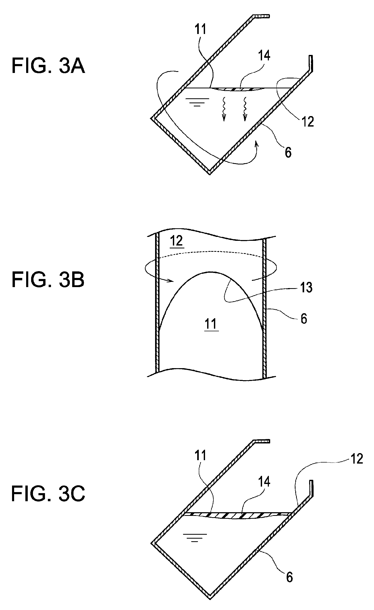
[0064]Even in this embodiment, the rotation driving portion 8 functioning as the external force applying portion moves the liquid level 11 of the waste liquid contained in the waste liquid tank 6 relative to the inner wall surface 12 of the waste liquid tank 6. That is, the liquid in the vicinity of the inner wall surface 12 rotates with a slight delay from the inner wall surface 12 by the rotation of the inner wall surface 12 of the waste liquid tank 6, and the delay is increased toward the center of the liquid level, that is, the axis. Accordingly, the liquid level 11 does not move by co...


PUM


Abstract

Provided is a waste liquid processing device including: a waste liquid tank collecting a liquid cured by irradiation of energy rays as a waste liquid; an irradiation portion irradiating curing energy rays to a liquid level of the waste liquid contained in the waste liquid tank; and an external applying portion applying external force to at least one of the waste liquid tank and the contained waste liquid.

Description

CROSS-REFERENCE TO RELATED APPLICATIONS[0001]This application claims priority under the Paris Convention based on Japanese Patent Application No. 2008-13437 (filed on Jan. 24, 2008).CROSS REFERENCES TO RELATED APPLICATIONS[0002]The present invention contains a subject matter related to Japanese Patent Application No. 2008-13437 filed in the Japanese Patent Office on Jan. 24, 2008, the entire contents of which are incorporated herein by reference.BACKGROUND[0003]1. Technical Field[0004]The present invention relates to a waste liquid processing device of an energy ray-curable liquid such as an energy ray-curable ink which is cured by irradiation of energy rays such as ultraviolet (UV) rays, and more particularly, a waste liquid processing device applicable to a liquid ejecting apparatus such as an ink jet recording apparatus for discharging ink droplets from nozzles in correspondence with print data so as to form dots on a recording medium.[0005]2. Related Art[0006]As a liquid ejectin...

Claims


Application Information

Patent Timeline
IPC IPC(8): B41J2/165
CPCB41J2/1721B41J2/185B41J2/17596
Inventor NORO, HIDEOKUMAGAI, TOSHIO
Owner SEIKO EPSON CORP
Learn More