Method and apparatus for capturing an image

a technology of image and capturing method, applied in the field of image capturing method and image capturing apparatus, can solve the problems of image distorted in the direction of scan, high cpu load, and high cost of additional circuitry, and achieve the effects of reducing cpu load, high quality image, and low cos

Inactive Publication Date: 2009-07-30
RPX CORP
View PDF3 Cites 12 Cited by
  • Summary
  • Abstract
  • Description
  • Claims
  • Application Information

AI Technical Summary

Benefits of technology

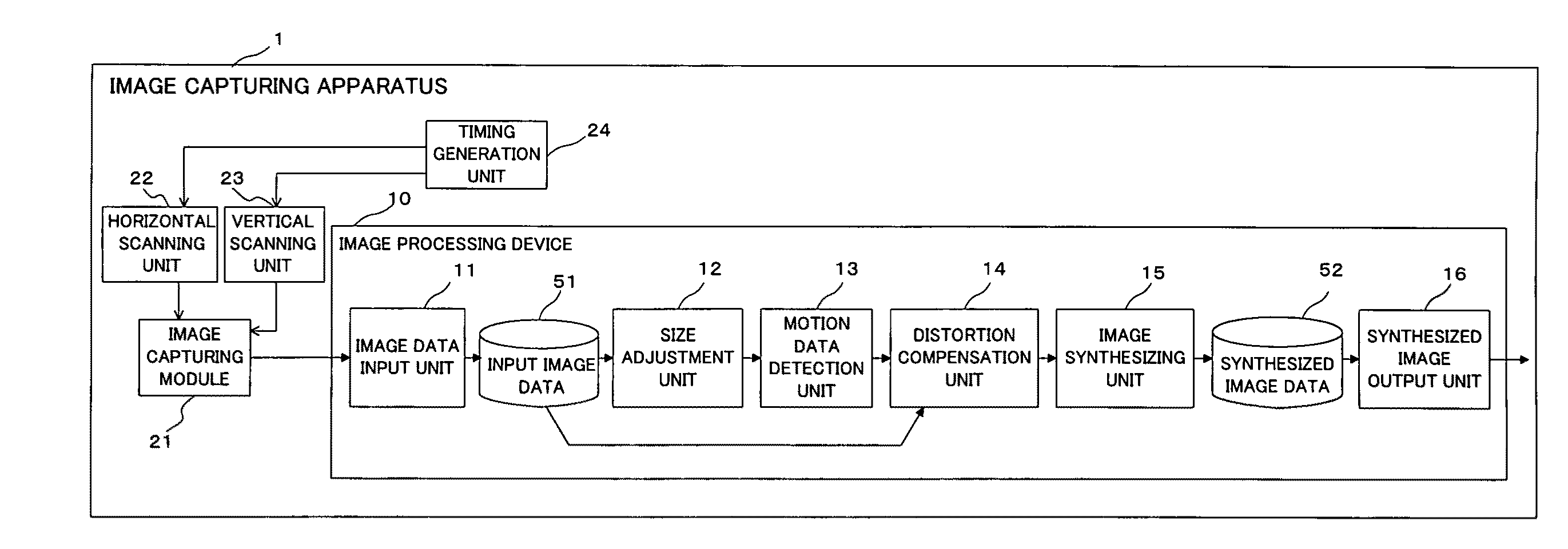
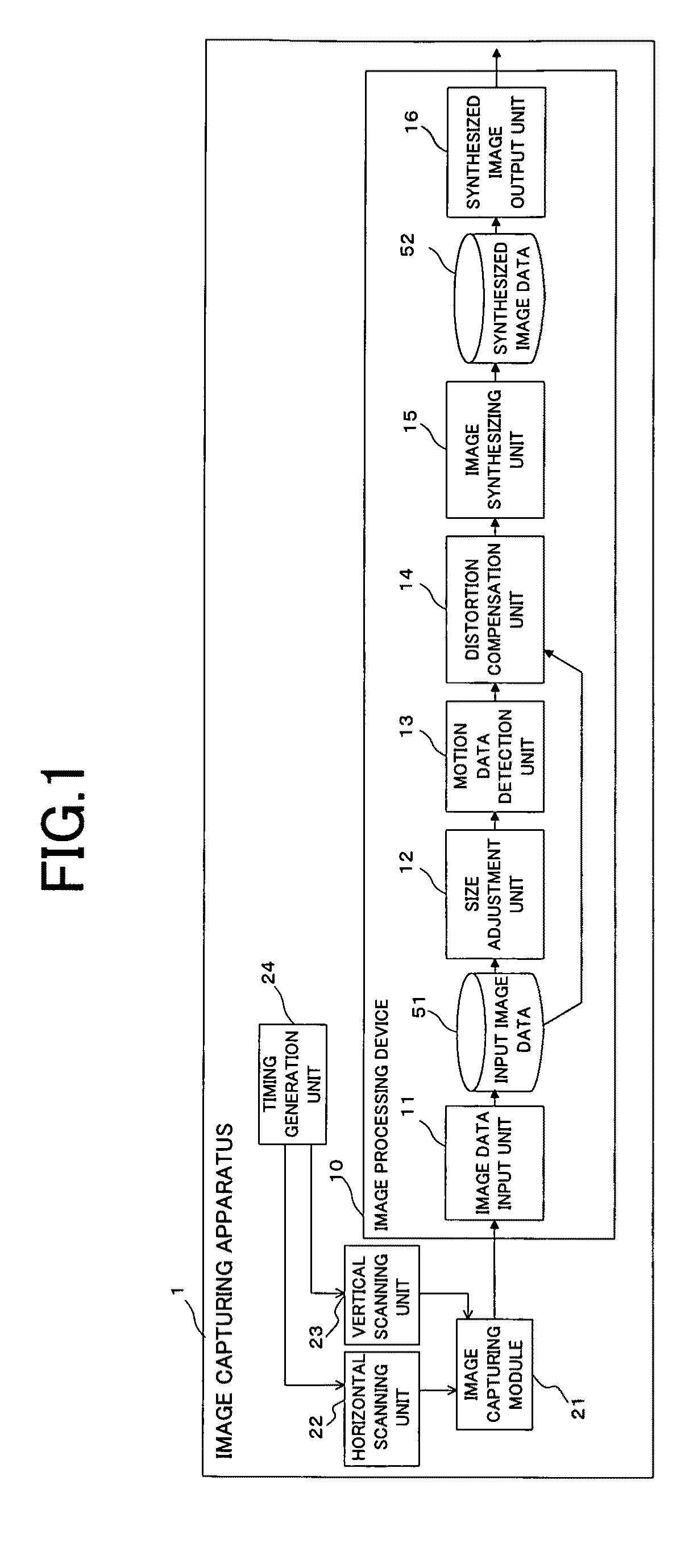
[0015]With the above circumstances taken into consideration, the object of the present invention is to provide a method and an apparatus for capturing an image that can create a high quality image at a low cost by reducing the CPU load associated with software image distortion-compensation for an image captured using a focal-plane electronic shutter system.

Problems solved by technology

Therefore, in a CMOS sensor, the timing of the output signal becomes delayed depending on the output electrical charge, which can cause an image to be distorted in the direction of the scan if camera-shake occurs during scanning.
However, these technologies require additional circuitry which is costly.
However, these methods require heavy CPU load, and they have limited accuracy in their compensation when a captured image is blurred at the time of it being captured.

Method used


Image

  • Method and apparatus for capturing an image
  • Method and apparatus for capturing an image
  • Method and apparatus for capturing an image

Examples


embodiment 2of

Another Embodiment 2of Motion Data Detection Process

[0065]In the above embodiment, the pixel skip mode image is used as a reference image against which each of the normal mode images are compared to as the target images in order to compute each motion data. However, as shown in FIG. 6, the motion data can be computed using just the pixel skip mode image (FIG. 6(a)) and the first normal mode image (FIG. 6(b)), and then compensate for the distortion in the normal mode image using this motion data. Then use this distortion compensated image (FIG. 6(d)) as the new reference image and the other normal mode images (FIG. 6(e)) as the target images to compute motion data between the images by using the block matching process, and this motion data can be used to compensate the distortion of normal mode images and then execute the blending process of the images.

embodiment 2

Another Embodiment 2 of Motion Data Detection Process

[0066]Motion data computation can be executed as shown in FIG. 7. First, interpolate the pixel skipped image by using methods such as the bilinear method or the bicubic method to resize it to be the same size as the normal mode images (FIG. 7(c)), and use this image as the reference image to compute the motion data between it and the normal mode images (FIG. 7(b)) to obtain the distortion compensated image (FIG. 7(d)). In this embodiment, motion data for high resolution images are calculated directly; therefore, the process to convert the motion data to the original image size becomes unnecessary.

[0067]The present invention shall not be limited to embodiments described above, and can be implemented in various forms that do not exceed the scope of the main purpose of this invention. For example, compensating the distortion in a single image captured in the normal mode can be executed by omitting the image synthesizing process.

[0068...


PUM


Abstract

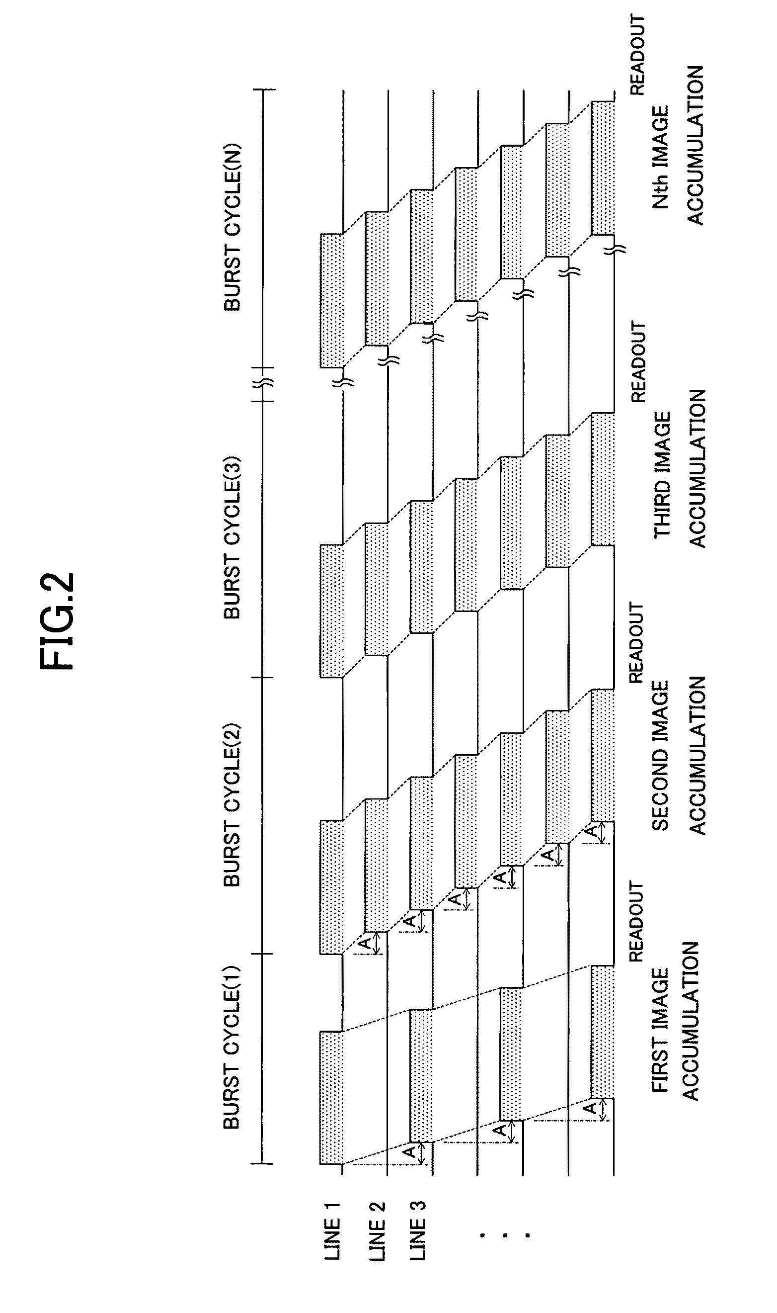
A method for capturing an image using an image capturing module with multiple pixels configured in a 2-dimensional matrix and a focal plane electronic shutter function which sequentially slides the exposure timing by constant interval by pixel group which is a unit of predetermined number of the pixels while scanning; the method includes an image data input process for detecting shutter operation, obtaining a reference image while skipping one or more of the pixel groups by sequentially sliding the exposure timing by the constant interval, and obtaining a target image while not skipping pixel groups to be captured, a motion data detection process for calculating the motion data of the target image based on the reference image, and a distortion compensation process for compensating for distortion in the target image according to the motion data.

Description

BACKGROUND OF THE INVENTION[0001]1. Field of the Invention[0002]The present invention relates to image capturing method and image capturing apparatus that compensates for distortions from such causes as camera-shake in an image captured by an image capturing device equipped with a CMOS type image capturing module, and creates a high quality distortion-compensated image.[0003]2. Description of the Related Art[0004]In recent years, image capturing module based on CMOS (Complementary Metal Oxide Semiconductor) sensors, which is smaller and requires less power compared to CCD (Charge Coupled Device), have been utilized in image capturing devices such as mobile phones and digital cameras.[0005]However, in a CMOS sensor image capturing module the focal plane electronic shutter system, which exposes and scans individual pixels and accumulated charges are output sequentially, is often used instead of the global electronic shutter system such as a CCD which simultaneously transfers every pix...

Claims


Application Information

Patent Timeline
Patent Type & Authority Applications(United States)
IPC IPC(8): H04N5/335G03B5/00H04N5/232H04N5/341H04N5/345H04N5/349H04N5/351H04N5/353H04N5/374H04N101/00
CPCH04N5/23232H04N5/2628H04N5/23248H04N5/23245H04N23/951H04N23/68H04N23/667
Inventor HIRAGA, MASAKIHABUKA, KENSUKE
Owner RPX CORP
Why Eureka
Try Eureka