Pillow block housing with tapered roller bearings

a technology of tapered roller bearings and hollow blocks, which is applied in the direction of sliding contact bearings, mechanical equipment, machines/engines, etc., can solve the problems of reducing the life affecting the installation and setup of spherical roller bearings, and large axial and radial deflections of spherical roller bearing systems, so as to facilitate assembly and ball-socket preload adjustment, the effect of convenien

Active Publication Date: 2009-07-30
THE TIMKEN CO
View PDF5 Cites 24 Cited by
  • Summary
  • Abstract
  • Description
  • Claims
  • Application Information

AI Technical Summary

Benefits of technology

[0009]Briefly stated, the present invention provides a spherical outer-diameter tapered roller bearing system for use in wind turbine main shaft support applications. The tapered roller bearing system is configured with a unitized construction and preload bearing settings to facilitate installation an

Problems solved by technology

However, spherical roller bearing systems have inherent problems.
In a wind turbine main shaft application, dynamically variable wind loads placed on the spherical roller bearing during operation cause large axial and radial deflections within the spherical roller bearing system as a result of the large radial internal clearance.
These deflections dramatically reduce spherical roller bearing life in an unpredictable manner due to a loss of load sharing to the rotor side roller row and wind vibration induced peeling and/or false brinelling of the raceway surfaces, which initiates premature raceway spalling.
The deflections further reduce bearing life of a downstream gearbox input shaft support due to excessive axial shaft deflection, which in turn leads to excessive thrust loads.
This large gap clearance red

Method used


Image

  • Pillow block housing with tapered roller bearings
  • Pillow block housing with tapered roller bearings
  • Pillow block housing with tapered roller bearings

Examples


Embodiment Construction

[0019]The following detailed description illustrates the invention by way of example and not by way of limitation. The description clearly enables one skilled in the art to make and use the invention, describes several embodiments, adaptations, variations, alternatives, and uses of the invention, including what is presently believed to be the best mode of carrying out the invention.

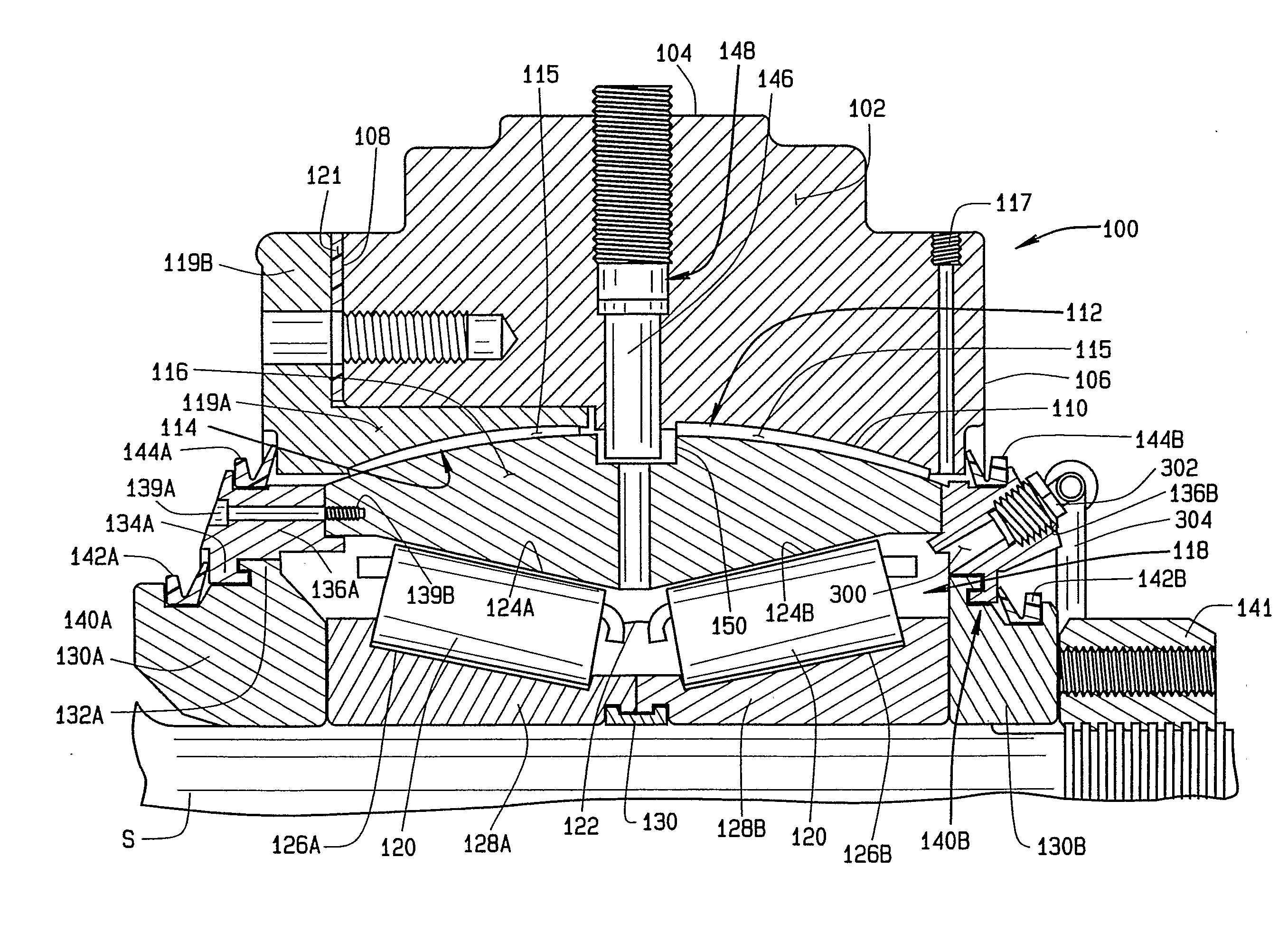
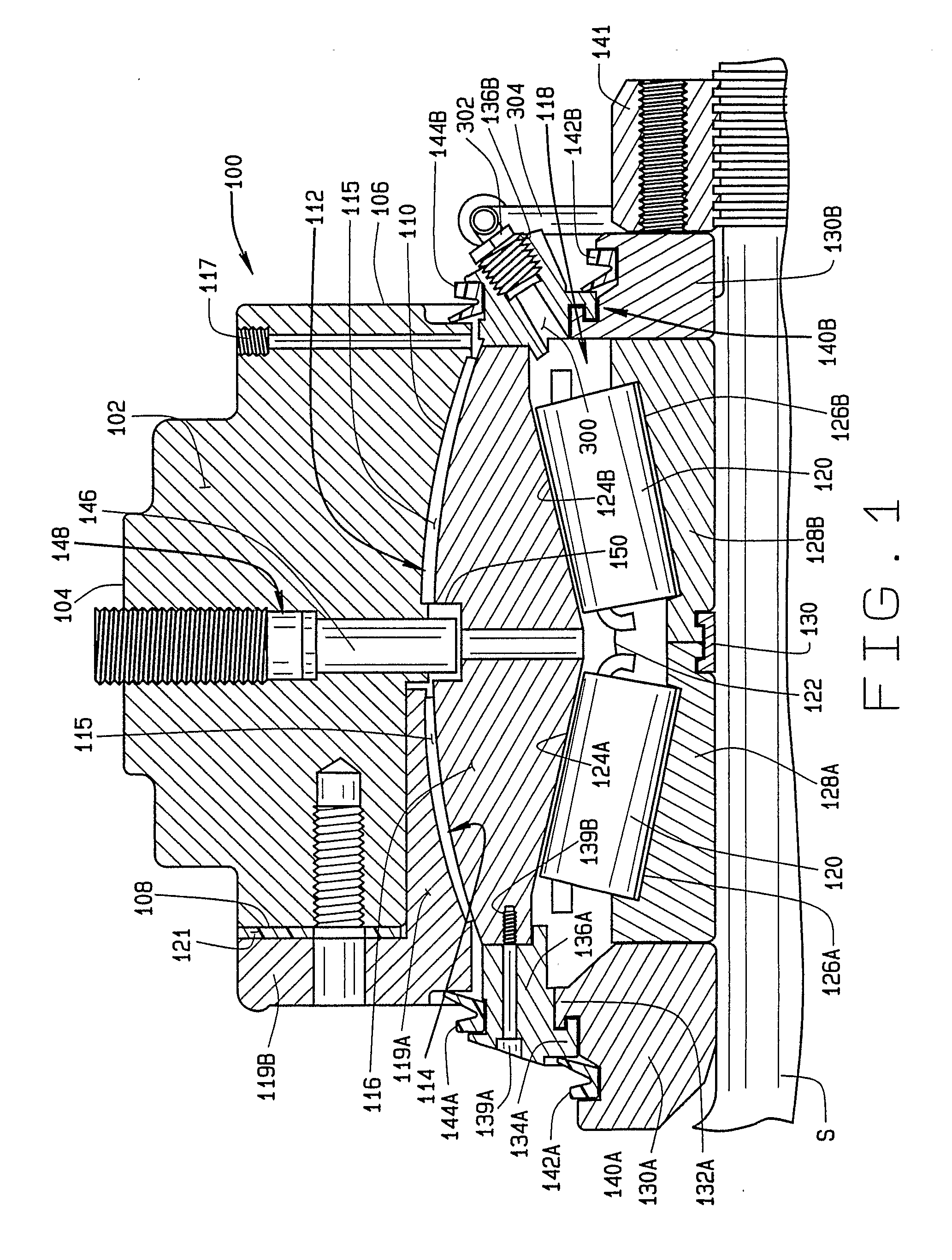
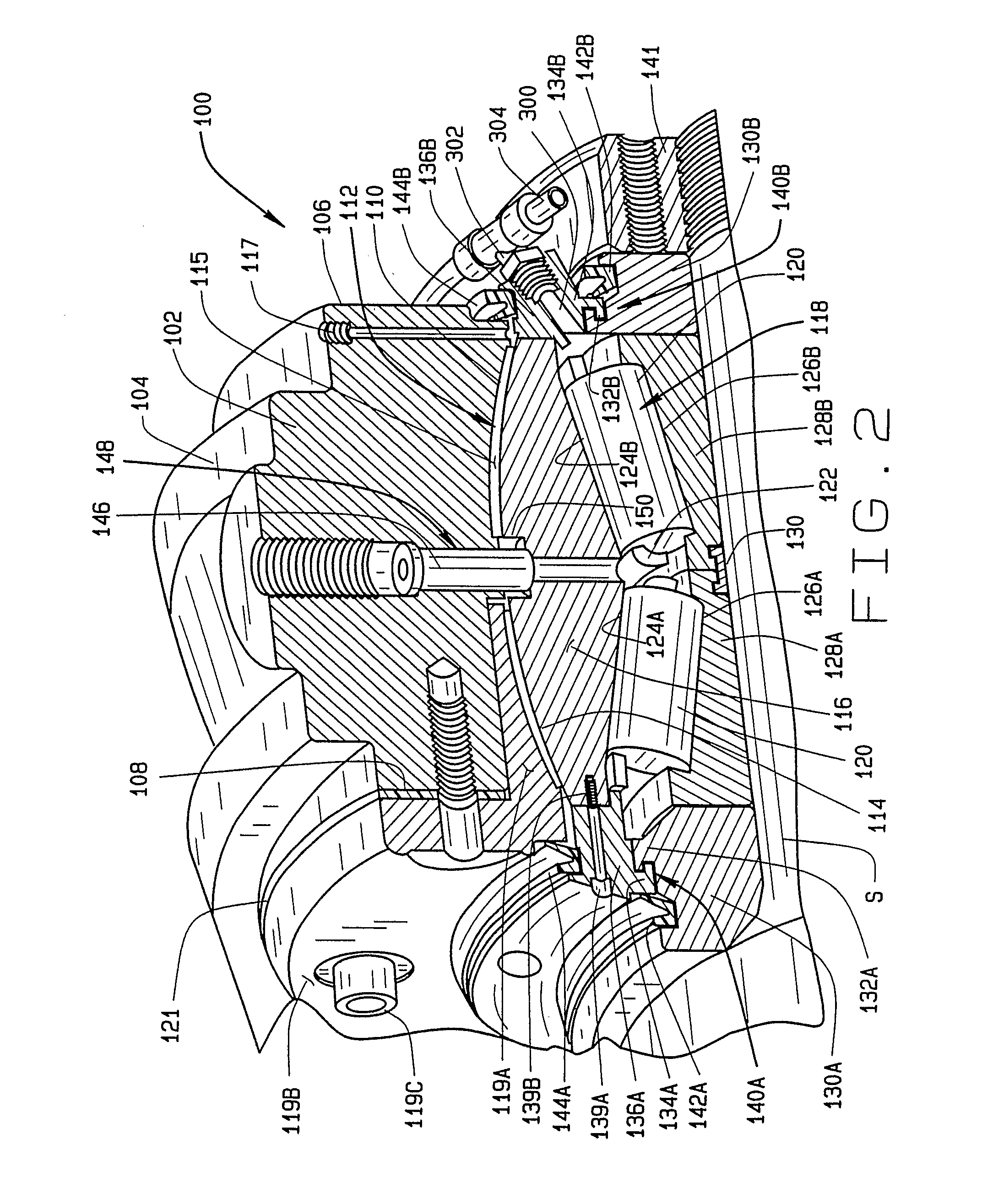
[0020]Turning to FIGS. 1-4, a first illustrative embodiment of a bearing assembly of the present invention for use in supporting a wind turbine main shaft is shown generally at 100. The bearing assembly 100 includes a pillow block housing 102 having an outer surface 104, a gear-box end surfaces 106, and a rotor-end surface 108. The outer surface 104 is configured with suitable attachments to couple the pillow block bearing assembly 100 to a supporting structure (not shown), preferably using a TDO (TNA) style mounting configuration which, by virtue of a larger effective spread and indirect mounting style, ...


PUM


Abstract

A spherical outer diameter tapered roller bearing pillow block system (100) for supporting the rotating main shaft of a wind turbine. The bearing system is configured with a unitized construction and factory set preload bearing settings to facilitate installation and setup. A spherical outer diameter surface (114) is formed on the Outer race (116) of a tapered roller bearing assembly disposed about the rotating main shaft of the wind turbine. The bearing assembly is secured to a stationary support structure of the wind turbine through a pillow block housing assembly (102) providing a matching spherical housing scat (112) to form a ball and socket interface between the tapered roller bearing assembly (118) and the pillow block housing assembly (102). The ball and socket interface accommodates static and dynamic misalignments between the wind turbine main shaft and the supporting structure, while the bearing assembly (118) accommodates radial and axial loads.

Description

CROSS-REFERENCE TO RELATED APPLICATIONS[0001]This application is related to, and claims priority from, U.S. Provisional Patent Application Ser. No. 60 / 659,805 filed on Mar. 9, 2005, and which is hereby incorporated by reference in entirety.TECHNICAL FIELD[0002]This invention relates to a bearing system for use in supporting the main shaft of a wind turbine assembly, and in particular, to a bearing system incorporating a spherical outer-diameter tapered roller bearing assembly secured within a pillow block system which is capable of carrying radial and axial loads, as well as static and dynamic angular misalignments of the supported main shaft for use in wind turbine applications.BACKGROUND OF THE INVENTION[0003]Within the wind power industry, it is common to utilize bearing systems for the wind turbine main shafts which are configured to handle large radial loads as well as large angular misalignments between a rotating shaft and the supporting bearing axis. These main shaft bearing...

Claims


Application Information

Patent Timeline
IPC IPC(8): F16C23/08F16C33/80
CPCF03D11/0008F16C19/386F16C23/084F16C33/6614F16C33/6622F16C33/80F16C2300/14F16J15/3456F16J15/4472Y02E10/722F16C33/7886F03D80/70F16C2360/31Y02E10/72
Inventor BURNER, BRUCE C.FOX, GERALD
Owner THE TIMKEN CO
Why Eureka
Try Eureka