Apparatus and methods for transporting and processing substrates

Active Publication Date: 2009-07-30
BOOKS AUTOMATION US LLC
View PDF37 Cites 62 Cited by
  • Summary
  • Abstract
  • Description
  • Claims
  • Application Information

AI Technical Summary

Benefits of technology

[0014]According to another aspect of the invention, a method for transferring wafers from a loadlock to a processing chamber via an evacuated transfer chamber is provided, comprising: providing a robot arm within the transfer chamber; magnetically coupling linear motion to the robot arm across a vacuum partition; magnetically coupling rotational motion to the robot arm across a vacuum partition; and reducing the speed of the rotational motion within the evacuated transfer chamber. The method may

Problems solved by technology

In part this is in recognition that the cost of manufacturing semiconductors is extremely high and costs are increasing.
The higher the costs the greater the risks in undertaki

Method used


Image

  • Apparatus and methods for transporting and processing substrates
  • Apparatus and methods for transporting and processing substrates
  • Apparatus and methods for transporting and processing substrates

Examples


Example

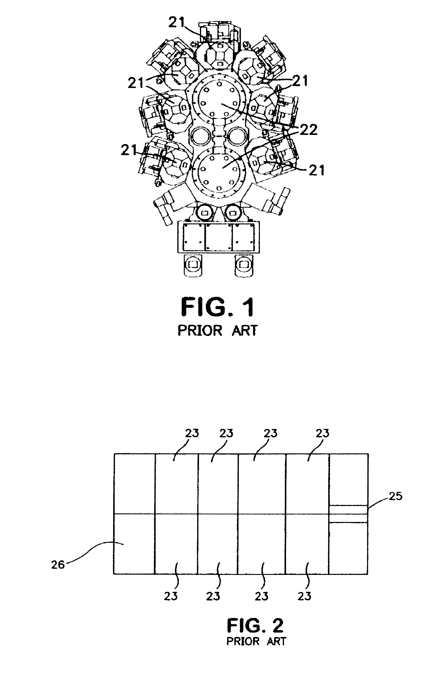
[0036]Referring now to FIG. 1, there is illustrated a cluster tool of the type commonly in use today. In general this comprises processing chambers 21 radially disposed around and attached to central chambers 22. In this system, there are two central chambers. Other systems may have only a single central chamber. A system with more than two can exist except that it is cumbersome and instead users will generally acquire another system. In operation, a robot is typically located within each central chamber 22. The robot receives wafers into the system and carries wafers from the central chamber to processing chambers and after processing back to the central chamber. In some prior art systems, a central robot can access only a single wafer and single chamber at one time. Thus the robot can become engaged or busy during processing in connection while a wafer is in a single chamber. This combination of a single robot tied to a processing station during processing is a limitation on the t...


PUM

PropertyMeasurementUnit
Speedaaaaaaaaaa

Abstract

There is described apparatus and methods for transporting and processing substrates including wafers as to efficiently produce at reasonable costs improved throughput as compared to systems in use today. A linear transport chamber includes linear tracks and robot arms riding on the linear tracks to linearly transfer substrates along the sides of processing chambers for feeding substrates into a controlled atmosphere through a load lock and then along a transport chamber as a way of reaching processing chambers.

Description

RELATED APPLICATIONS[0001]This application is a Continuation-in-Part of U.S. application Ser. No. 11 / 523,101 filed Sep. 19, 2006 and U.S. application Ser. No. 12 / 325,993 filed Dec. 1, 2008, the disclosures of which are incorporated herein by reference in their entirety.FIELD OF THE INVENTION[0002]This invention has to do with novel apparatus and methods for transporting and processing substrates in general and wafers in particular.BACKGROUND[0003]In the manufacture of semiconductors, a common tool, referred to as a cluster tool, is one of the key units used in the manufacture of wafers. A typical commercial device has a generally circular central area with chambers attached along the circumference. The chambers extend outward around the central area. When wafers are processed they are moved first from an input output station on the circumference of the central chamber into the central chamber and then from the central chamber into an attached or circumferential chamber where process...

Claims


Application Information

Patent Timeline
IPC IPC(8): H01L21/677
CPCC23C14/568C23C16/545H01L21/67745H01L21/67184H01L21/67201H01L21/67173C23C16/54H01L21/67167H01L21/67196H01L21/67709
Inventor BLUCK, TERRYFAIRBAIRN, KEVIN P.BARNES, MICHAEL S.LANE, CHRISTOPHER T.
Owner BOOKS AUTOMATION US LLC
Why Eureka
Try Eureka