Hand-Guided Power Tool

Active Publication Date: 2009-08-06
ANDREAS STIHL AG & CO KG
View PDF20 Cites 51 Cited by
  • Summary
  • Abstract
  • Description
  • Claims
  • Application Information

AI Technical Summary

Benefits of technology

[0004]It is an object of the present invention to improve a hand-guided power tool of the aforementioned k

Problems solved by technology

When the braking device is applied, i.e., the brake drum is blocked and cannot rotate, switching on the electric motor can cause overload of the motor or of the braking device.
When the band brake is applied

Method used


Image

  • Hand-Guided Power Tool
  • Hand-Guided Power Tool
  • Hand-Guided Power Tool

Examples


Example

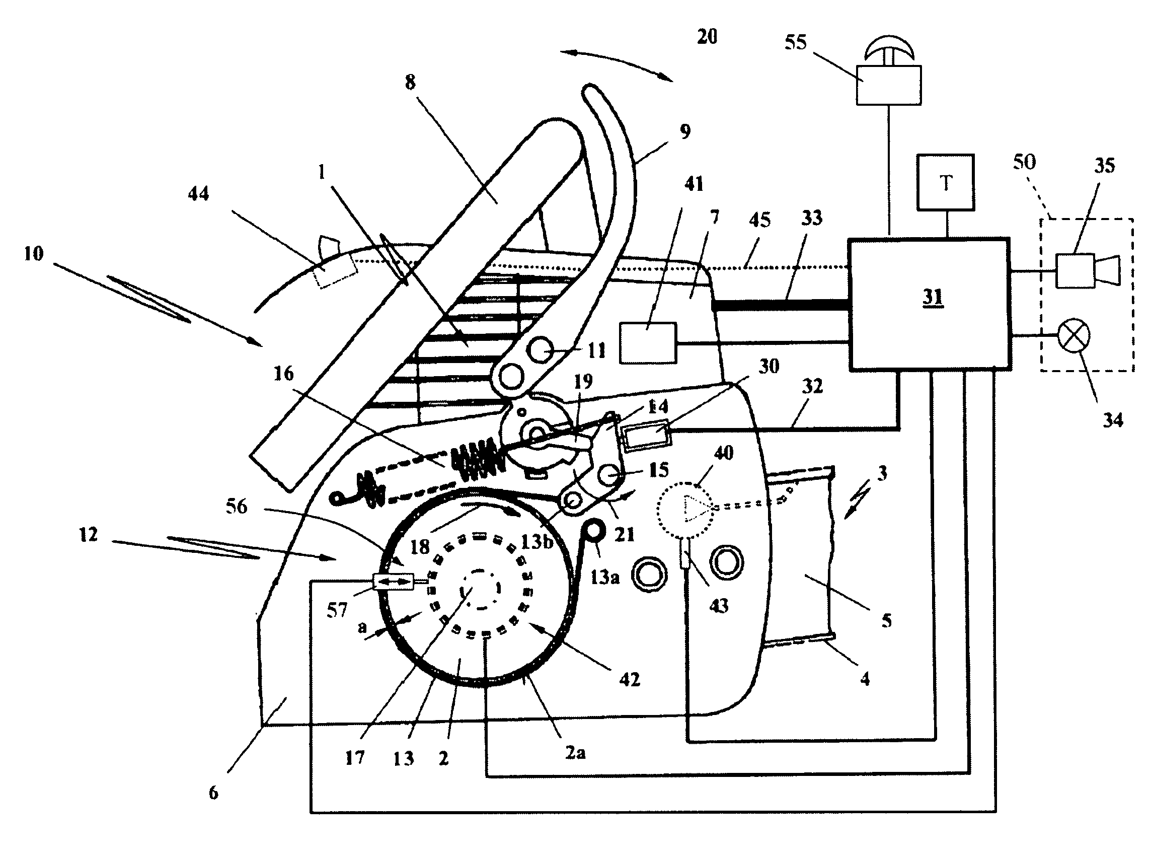
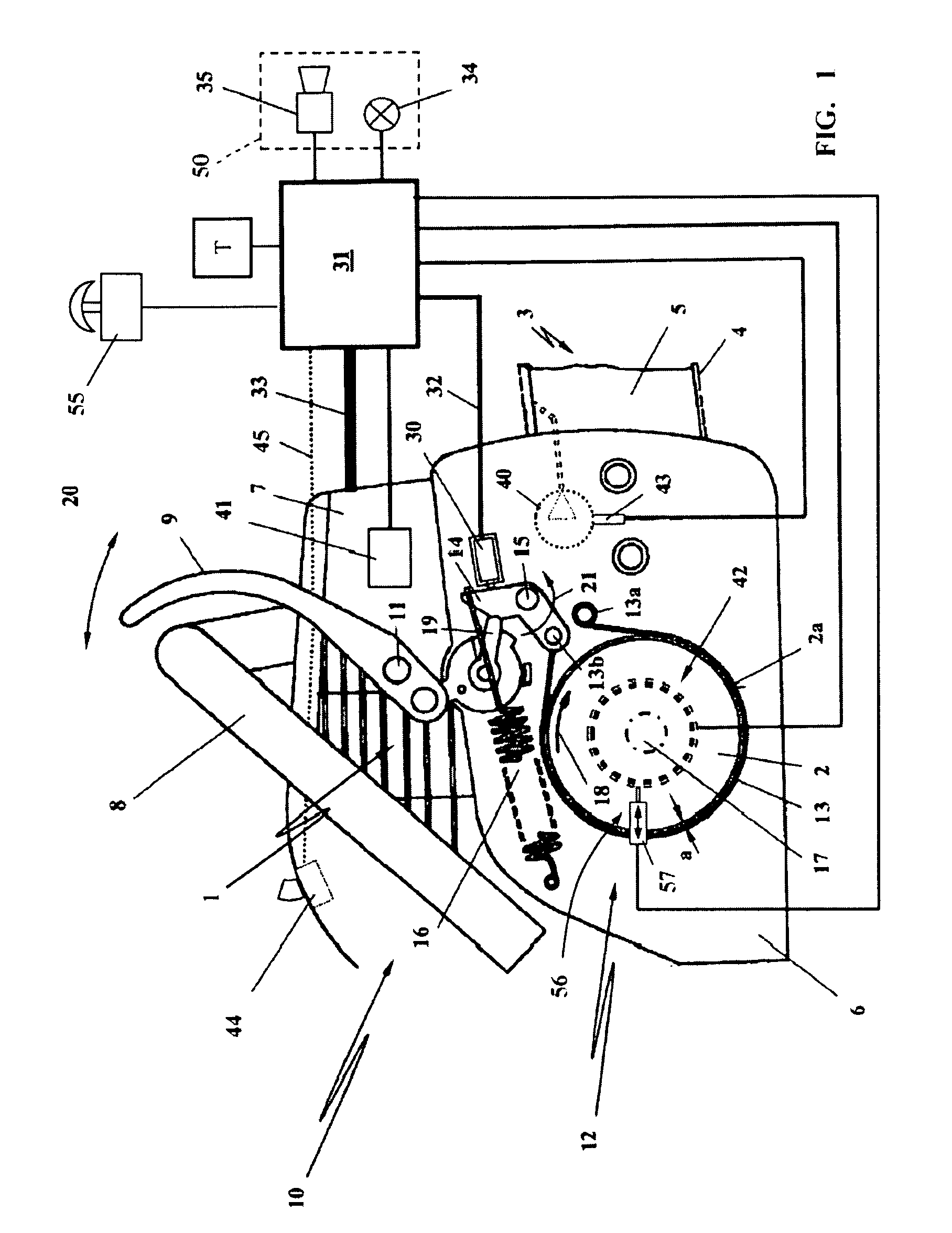
[0021]FIG. 1 shows schematically a motor chain saw as an example of a hand-guided power tool which, of course, could also be a cut-off machine, a hedge trimmer, a trimmer / brushcutter or the like.

[0022]The illustrated hand-guided power tool 10 has a drive motor 1 that drives by means of a rotating drive element 2 a working tool 3. In the illustrated embodiment the rotating drive element 2 is a clutch drum, for example, of a centrifugal clutch on which a sprocket wheel (not illustrated in detail) is fixedly arranged. The non-illustrated sprocket wheel drives a saw chain 4 that circulates about guide bar 5. Guide bar 5 is clamped between a sprocket wheel cover 6 and a housing 7 of the motor chainsaw.

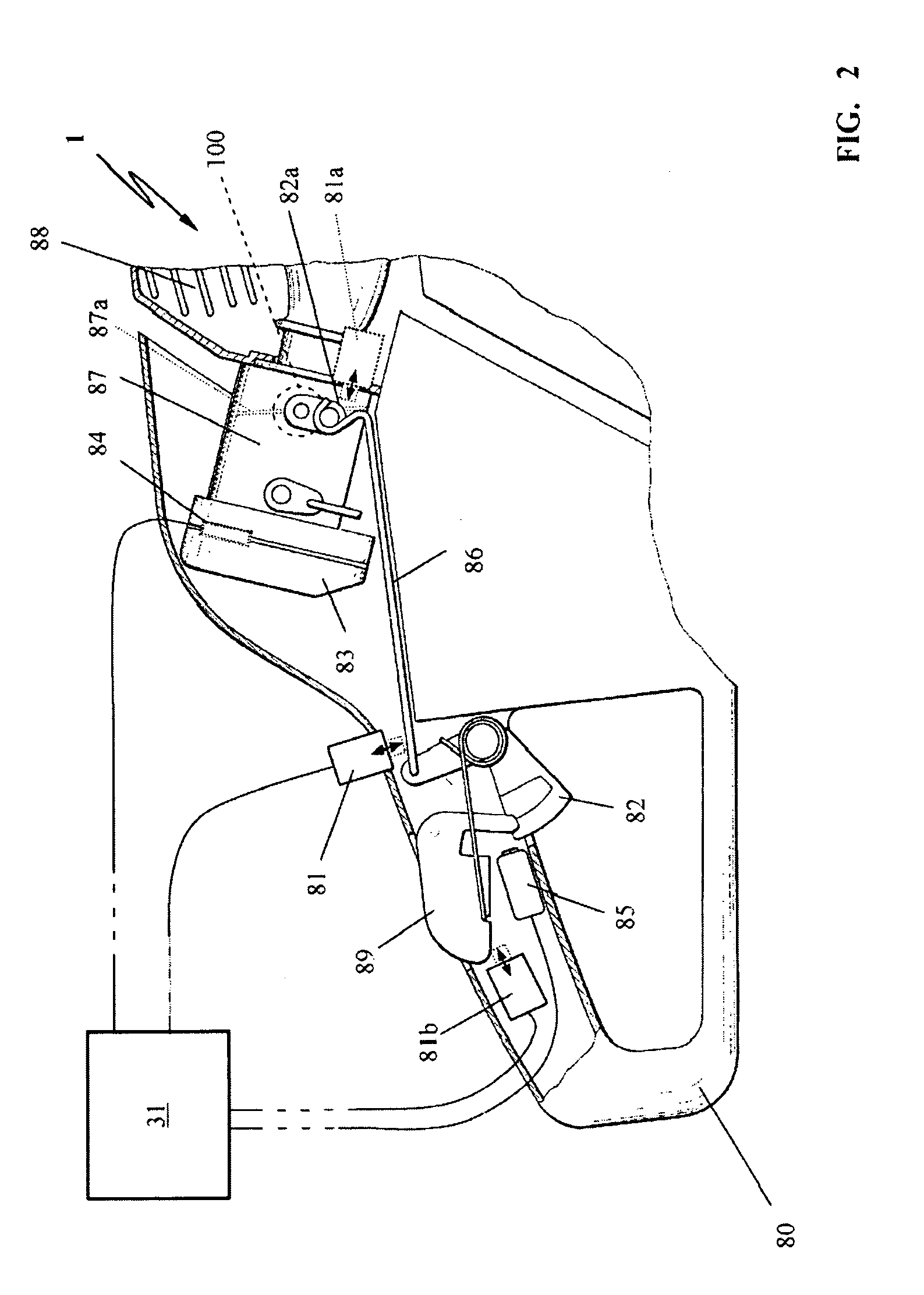
[0023]The power tool 10 is held by the operator by means of two handles: rear handle 80, illustrated in FIG. 2, as well as front handle 8 that spans the housing 7. In front of the handle 8 there is a hand guard 9 that is arranged to be pivotable about axis 11 on the housing 7 and serves as ...


PUM

PropertyMeasurementUnit
Speedaaaaaaaaaa

Abstract

A hand-guided power tool has a drive motor and a drive element connected to and driven by the drive motor. A working tool is connected to the drive element and driven by the drive element. A braking device is correlated with the drive element, wherein the braking device in a first state, in which the braking device is applied, blocks the drive element and in a second state, in which the braking device is released, releases the drive element so that the drive elements can rotate freely. The braking device has a brake lever and a sensor that detects the first and second states of the braking device. A control unit is provided, wherein an output signal of the sensor as a state signal of the first state or the second state is supplied to the control unit. The control unit, based on the state signal, controls devices of the power tool.

Description

BACKGROUND OF THE INVENTION[0001]The invention relates to a hand-guided power tool, in particular, a motor chain saw, a cut-off machine, a hedge trimmer, a trimmer / brushcutter or the like, comprising a drive motor that drives a working tool by means of a rotating drive element. A braking device is correlated with the rotating drive element; in a first applied state the braking device brakes the drive element and in a second released state the braking element allows the drive element to rotate, wherein the braking device comprises a brake lever.[0002]U.S. Pat. No. 4,662,072 discloses a motor chain saw whose drive motor is an electric motor and drives by means of a sprocket wheel used as a drive element a working tool, i.e., a saw chain circulating on the guide bar. As a braking device a band brake is provided that acts on a brake drum connected fixedly to the drive shaft. When the braking device is applied, i.e., the brake drum is blocked and cannot rotate, switching on the electric ...

Claims


Application Information

Patent Timeline
IPC IPC(8): B27B17/08
CPCB27B17/083F02N11/10Y10T83/086
Inventor GORENFLO, ERNST
Owner ANDREAS STIHL AG & CO KG
Why Eureka
Try Eureka