Fuel Supply System for a Vehicle Including a Vaporization Device for Converting Fuel and Water into Hydrogen

a technology of hydrogen and fuel supply system, which is applied in the direction of liquid fuel feeder, machine/engine, mechanical apparatus, etc., can solve the problems of high carbon monoxide emissions from the exhaust of these engines, the inability to achieve fuel economy at the expense of the power and size of the vehicle, and the contribution of conventional internal combustion engines to the environmen

Inactive Publication Date: 2009-08-06
TYMA
View PDF12 Cites 30 Cited by
  • Summary
  • Abstract
  • Description
  • Claims
  • Application Information

AI Technical Summary

Problems solved by technology

Typically, however, such fuel economy can only be achieved at the expense of power and size of the vehicle.
Also, conventional internal combustion engines contribute significant amounts of pollution to the environment, particularly in large cities where there are many vehicles on the road.
Further, the exhaust from these engines includes dangerous levels of carbon monoxide.
One problem experienced with the use of such vaporization devices is that the spark plugs, engine cylinders, and valves would quickly become blackened with soot, which was believed to be carbon.
A problem with such electric vehicles is that they do not have the range of a vehicle powered by an internal combustion engine.
Also, the batteries may take a relatively long time to recharge.
Because people have grown accustomed to the greater range and refueling convenience of vehicles powered with internal combustion engines, electric vehicles have not been widely accepted by the public.
While hybrid electric vehicles show much promise, they nevertheless still utilize an engine that pollutes the atmosphere and generates dangerous levels of carbon monoxide.
The use of alternative fuels has not become widely commercialized, however, due to their requirements that the current infrastructure would require change.
Also, alternative fuels such as methane and hydrogen are combustible gasses that would have to be stored in a pressurized container within the vehicle and, therefore, would pose a severe danger to the vehicle occupants.
Clearly, such systems cannot immediately generate hydrogen when the engine is cold or on ignition start-up.
Some of these systems rely upon an expensive catalyst, such as platinum, to convert hydrocarbons to hydrogen.
Again, the use of such pressurized hydrogen storage tanks is not desirable due to the hazard it presents.
However, the heat required to produce steam from stored water, which may be cold, is not immediately available on cold engine start-up.
This thermal energy is wasted as dissipated heat.

Method used


Image

  • Fuel Supply System for a Vehicle Including a Vaporization Device for Converting Fuel and Water into Hydrogen
  • Fuel Supply System for a Vehicle Including a Vaporization Device for Converting Fuel and Water into Hydrogen
  • Fuel Supply System for a Vehicle Including a Vaporization Device for Converting Fuel and Water into Hydrogen

Examples


Embodiment Construction

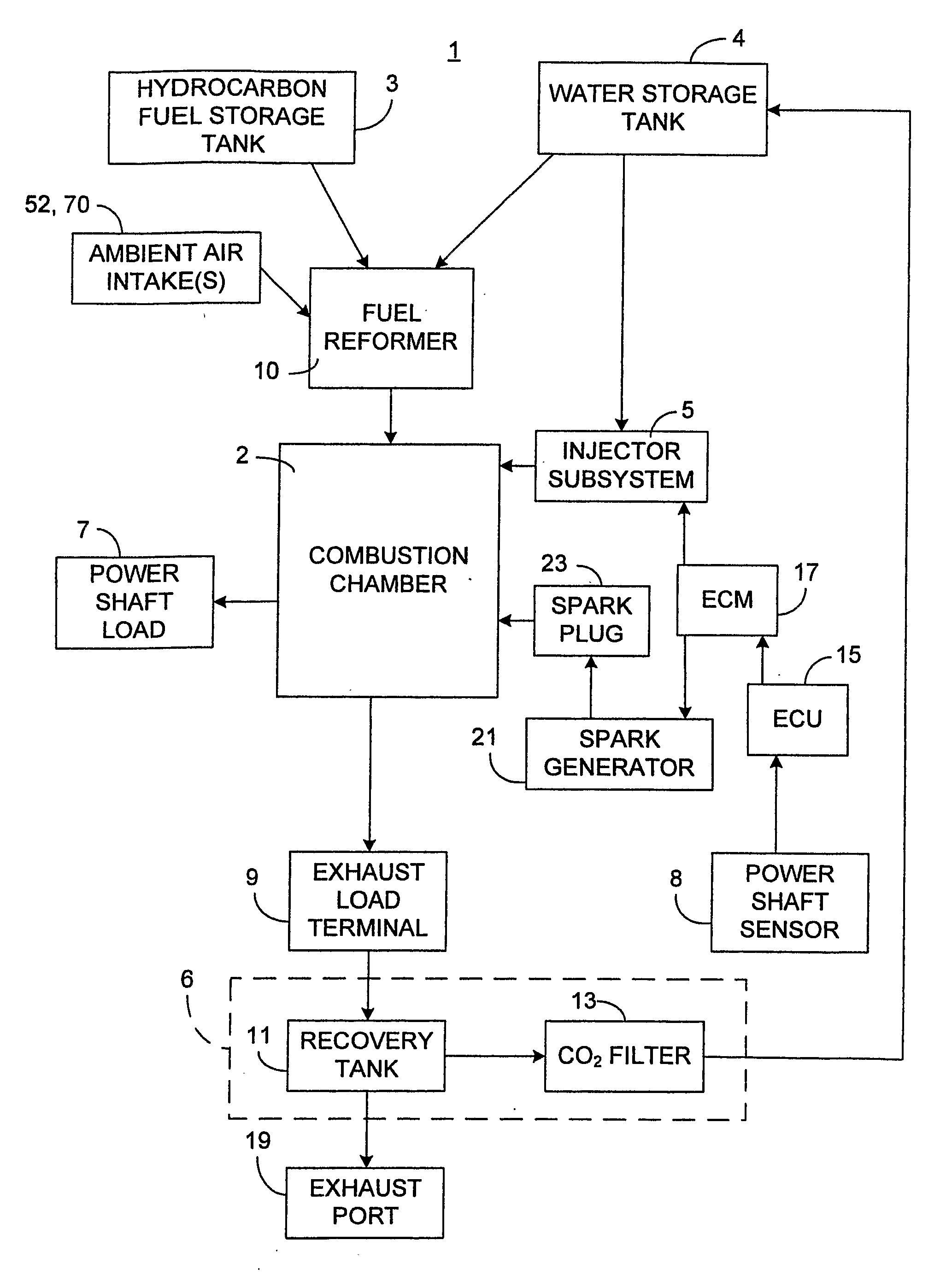
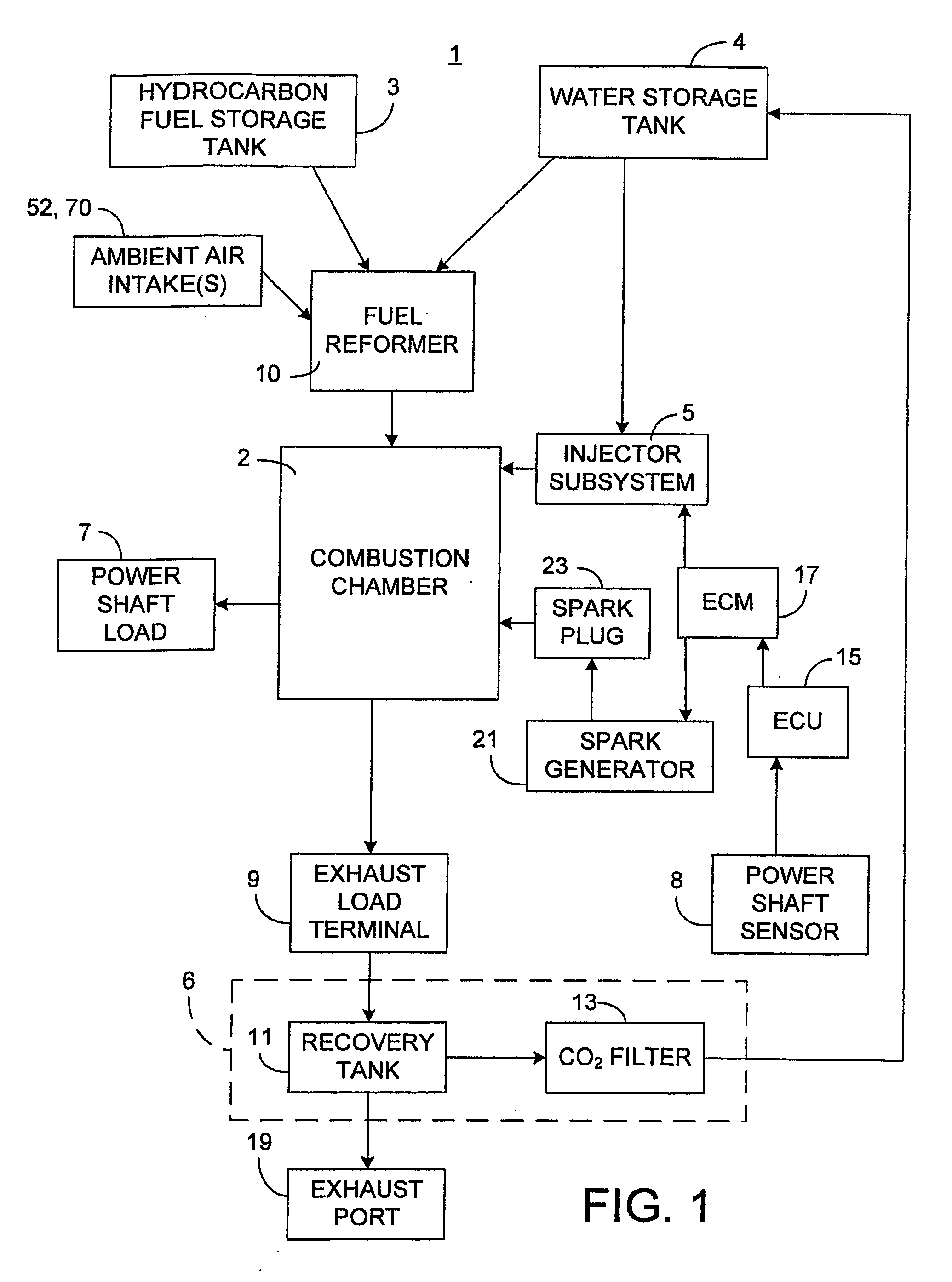
[0024]The present invention provides an improved fuel supply system that uses the novel fuel reformer of U.S. Pat. No. 6,508,201, while improving upon the prior fuel supply system by utilizing the large amount of thermal energy that is created upon igniting the hydrogen gas introduced into the engine's cylinders. In particular, the present invention converts the generated thermal energy into a physical force that further drives the pistons of the engine.

[0025]As described in detail below, the fuel supply system 1 of the present invention is designed to inject water into each cylinder of an internal combustion engine immediately after ignition of the hydrogen at or before top dead center. Preferably, the water is injected into the combustion chamber 2 of each cylinder at 12 degrees of the crank shaft 7 rotation after spark ignition within that cylinder. The thermal energy generated by the ignition of the hydrogen converts the injected water into steam, which rapidly expands in the li...


PUM


Abstract

A fuel supply system (1) is disclosed for use with an internal combustion engine or a fuel cell system (408). The fuel supply system may include a water supply (4) for supplying water; a fuel supply (3) for supplying fuel; a fuel reformer (10) including an air inlet (52,70) converts the water, air, and fuel into hydrogen and byproducts, and supplies the hydrogen to combustion chambers (2) of an internal combustion engine; and an injector subsystem (5) coupled to the water supply injects water into the combustion chambers following ignition of the hydrogen in the combustion chambers. The fuel supply system may include a water recovery subsystem (6) coupled to an exhaust output (9) of the internal combustion engine, the internal combustion engine producing an exhaust including water vapor and CO2, the water recovery subsystem comprising a filter (13) for removing CO2, from the water vapor.

Description

BACKGROUND OF THE INVENTION[0001]The present invention generally relates to a fuel supply system for a vehicle and more particularly to a system supplying fuel to an internal combustion engine or fuel cell of an automotive vehicle or electrical generator.[0002]Ever since the advent of automotive vehicles, those who design and manufacture automotive vehicles have had the goal of producing a propulsion system that minimizes use of fossil fuels and does not generate byproducts that are harmful to humans or the environment. The majority of conventional automotive vehicles include an internal combustion engine that is fueled by gasoline or diesel fuel. These automotive vehicles generally can travel relatively significant distances between refueling and can obtain up to about 50 miles per gallon of gasoline. Typically, however, such fuel economy can only be achieved at the expense of power and size of the vehicle. Also, conventional internal combustion engines contribute significant amoun...

Claims


Application Information

Patent Timeline
Patent Type & Authority Applications(United States)
IPC IPC(8): F02B47/02F02M69/04F01N3/02
CPCF02B43/10F02B47/02F02M25/12F02M25/0228Y02T10/32F02M25/0224Y02T10/121Y02T10/12Y02T10/30
Inventor WORKMAN, ALAN J.KNOWLTON, JAMES L.KNOWLTON, DONALEE
Owner TYMA
Why Eureka
Try Eureka