Integrated circuit

Active Publication Date: 2009-08-06
THRUCHIP JAPAN INC
View PDF10 Cites 22 Cited by
  • Summary
  • Abstract
  • Description
  • Claims
  • Application Information

AI Technical Summary

Benefits of technology

[0036]According to the integrated circuit of the fifth aspect of the present invention, a desired bias voltage can b

Problems solved by technology

However, because the pulse of received voltage VR shown in FIG. 12 is a positive and negative double pulse to one logic transition of the transmission signal

Method used


Image

  • Integrated circuit
  • Integrated circuit
  • Integrated circuit

Examples


Embodiment Construction

[0049]Hereinafter, a detailed description is given of a best mode for carrying out the present invention with reference to the accompanying drawings.

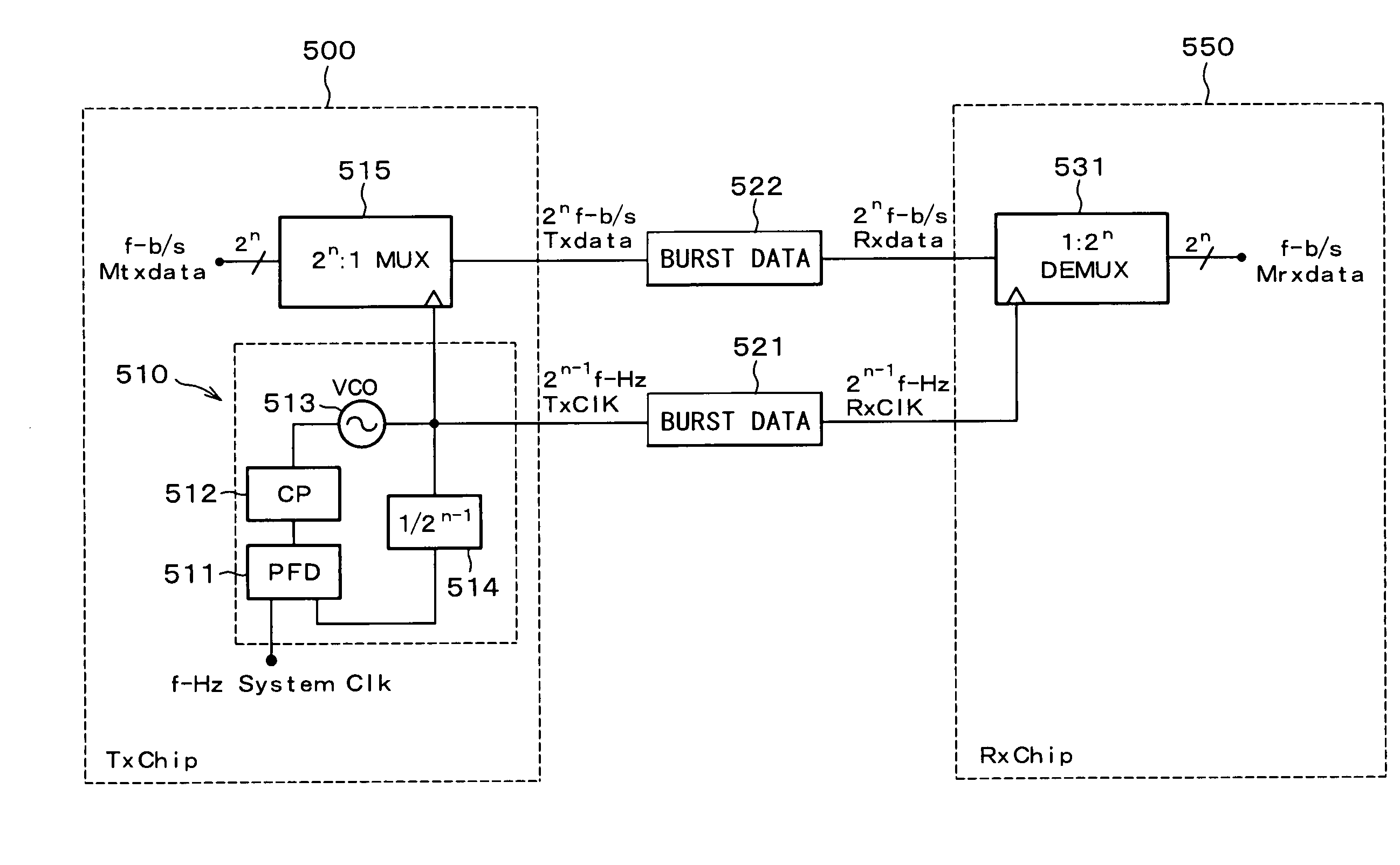
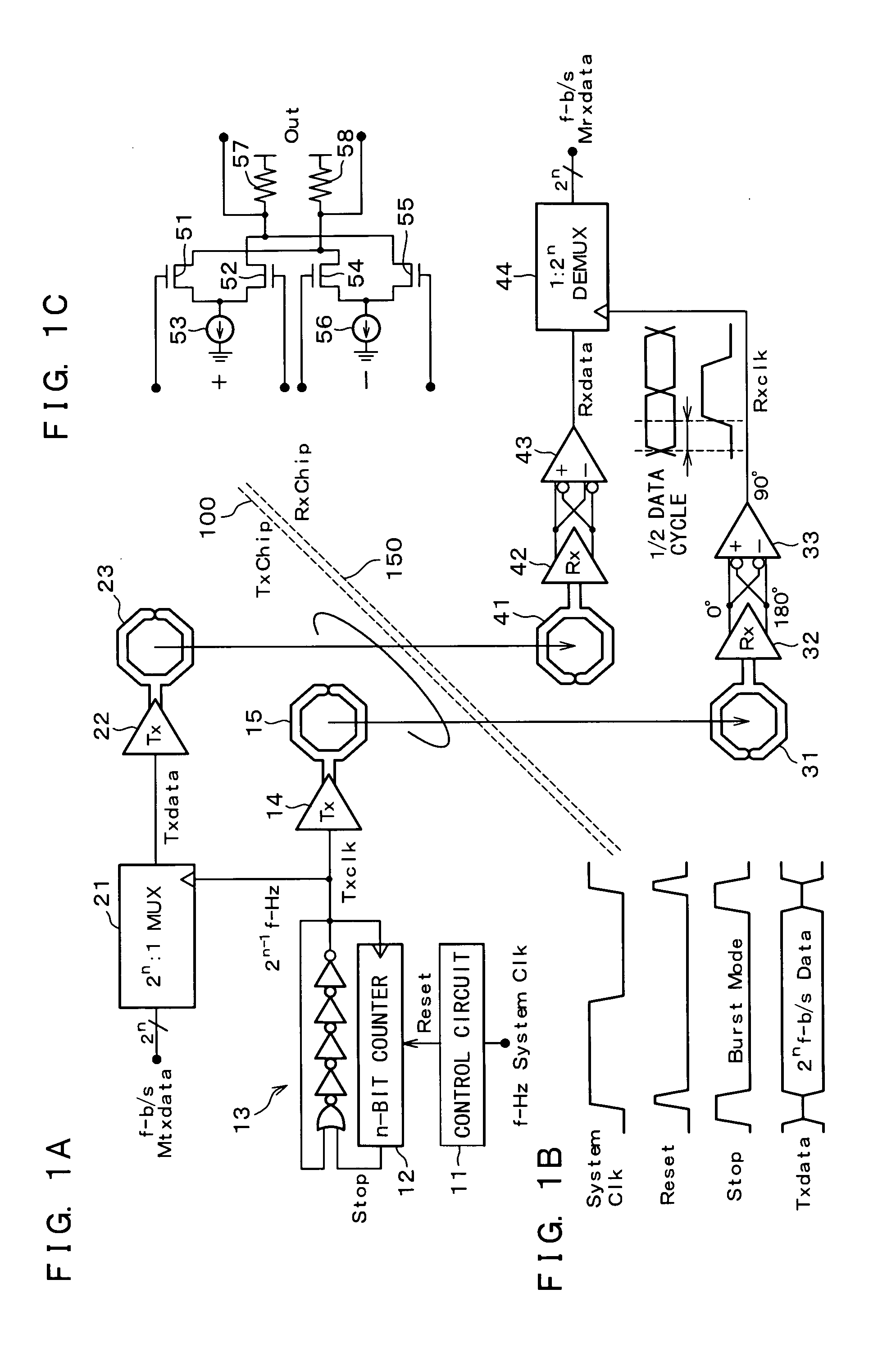
[0050]FIG. 1A, FIG. 1B, and FIG. 1C are views depicting a configuration of an integrated circuit according to one embodiment of the present invention. FIG. 1A depicts a configuration of the embodiment, FIG. 1B depicts waveforms of respective portions of the embodiment, and FIG. 1C depicts a configuration of a phase interpolator. A transmitter chip 100 is composed of a control circuit 11, an n-bit counter 12, a ring oscillator 13, a transmitter circuit 14, a transmitter coil 15, a 2n:1 multiplexer 21, a transmitter circuit 22, and a transmitter coil 23. An operation to generate a transmission timing pulse Txclk and an operation to demultiplex transmission data Mtxdata are the same as those shown in FIG. 7. In the present embodiment, the transmission timing pulse Txclk is transmitted to a receiver chip 150 by inductive coupling via the tr...


PUM


Abstract

An integrated circuit multiplexes transmission data faster than by a system clock, and transfers a timing pulse Txclk for that multiplexing and a multiplexed signal Txdata from a transmitter chip 100 to a receiver chip 150 through communications by inductive coupling, respectively. Because of a transfer by inductive coupling being broadband, close-proximity wireless communications, the receiver chip 150 can faithfully obtain timing information on the timing pulse Txclk including jitter generated by a simple oscillator, and can thus accurately restore original data even by a high-speed transmission. This allows, in an integrated circuit that carries out communications by inductive coupling between chips to be stacked and mounted, carrying out communications between semiconductor chips with a small required area and faster than by a system clock.

Description

BACKGROUND OF THE INVENTION[0001]1. Field of the Invention[0002]The present invention relates to an integrated circuit that is capable of suitably carrying out communications between chips such as IC (Integrated Circuit) bare chips to be stacked and mounted.[0003]2. Description of the Related Arts[0004]The present inventors have proposed electronic circuits that carry out communications by inductive coupling between chips to be stacked and mounted via coils formed by on-chip wiring of LSI (Large Scale Integration) chips (refer to Patent Literature 1).[0005]FIG. 5 is a view depicting a configuration of a conventional (first) transmitter and receiver circuit. A part thereof is shown also in Patent Literature 1. FIG. 6 is a view depicting waveforms of respective portions of the circuit shown in FIG. 5. A transmitter circuit 300 is composed of a pulse generator 311, an inverter 312, a NOR circuit 313, transistors 314, 315, an inverter 316, a NOR circuit 317, transistors 318, 319, and a ...

Claims


Application Information

Patent Timeline
IPC IPC(8): H04J3/06
CPCH04J3/047H01L2924/0002H01L2924/00
Inventor KURODA, TADAHIRO
Owner THRUCHIP JAPAN INC
Why Eureka
Try Eureka