Multiferroic element

a multi-ferroic element and multi-ferroic technology, applied in the field of multi-ferroic elements, can solve the problem that the orientation of a solid-state material magnetization cannot be reversed by an electric field, and achieve the effect of simple structur

Inactive Publication Date: 2009-08-06
JAPAN SCI & TECH CORP +1
View PDF8 Cites 34 Cited by
  • Summary
  • Abstract
  • Description
  • Claims
  • Application Information

AI Technical Summary

Benefits of technology

[0005]By taking the situation described above into account, the purpose of the present invention is to provide a multiferroic element having a simple structure in which an orientation of an electric polarization or a magnetization of a solid state material can be controlled by applying a magnetic field or an electric field, respectively.

Problems solved by technology

Conversely, an orientation of a magnetization in a solid state material was not able to be reversed by an electric field, either.

Method used


Image

  • Multiferroic element
  • Multiferroic element
  • Multiferroic element

Examples


Embodiment Construction

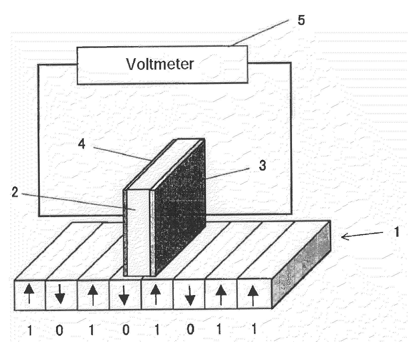
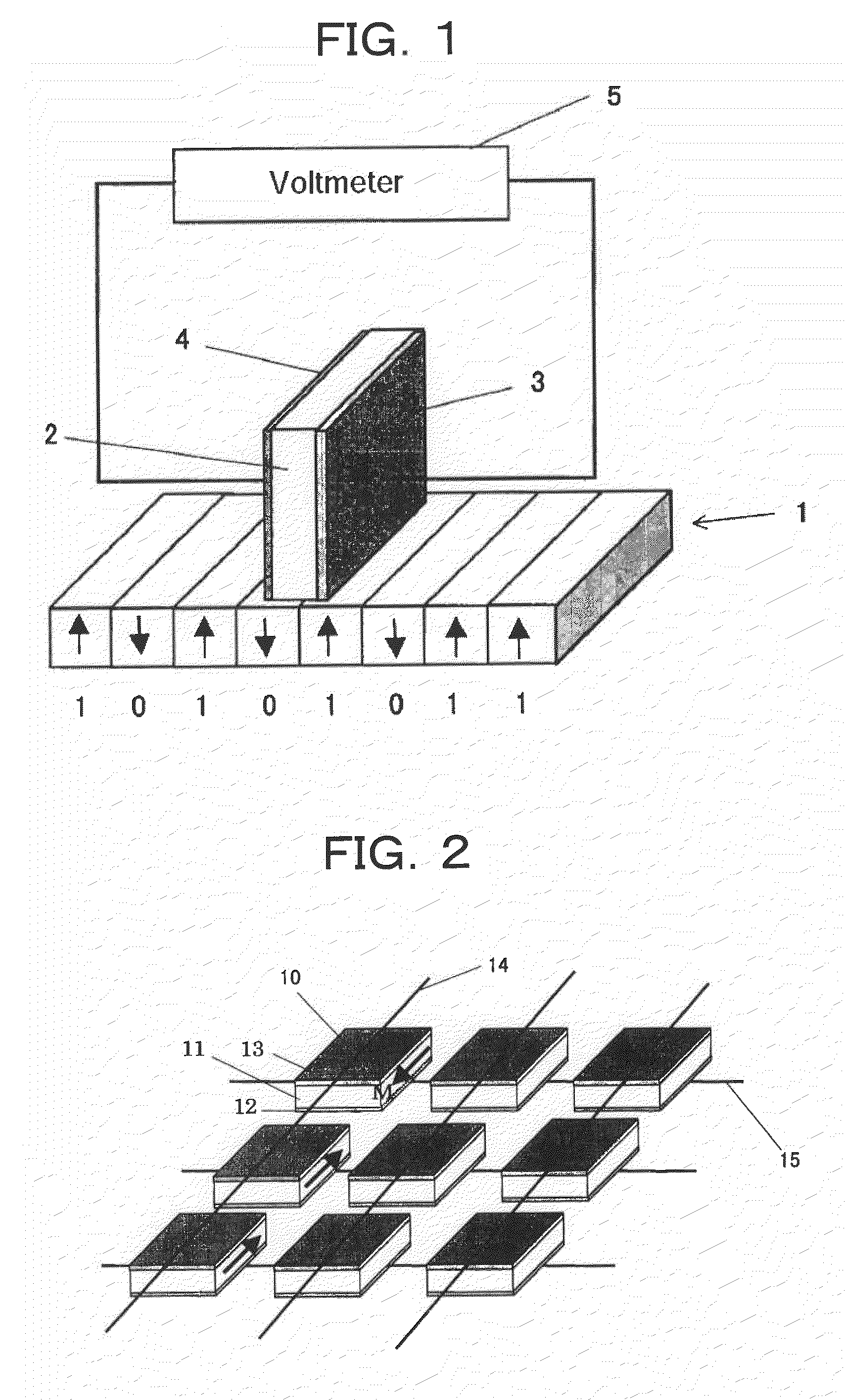
[0018]A structure of a multiferroic magnetic sensor element as shown in FIG. 1 may have a structure comprising a multiferroic solid state material sandwiched by two metallic electrodes using a voltmeter to detect an electric polarization being generated by a magnetic field leaked from the magnetization corresponding to information and being oriented substantially perpendicular to said magnetic field.

[0019]Furthermore, a multiferroic memory element comprises a multiferroic solid state material sandwiched between two metallic electrodes as shown in FIG. 2. By applying a voltage between a specifically selected bit line and a word line, a magnetization generates in the specified orientation in the single memory element sandwiched between the selected lines. The generated magnetization has a memory function. The space between the memory elements is of a buried structure filled by a non-magnetic solid state material.

[0020]Embodiments of the present invention will be described in the follo...


PUM

PropertyMeasurementUnit
temperatureaaaaaaaaaa
frequencyaaaaaaaaaa

Abstract

A multiferroic element having a simple structure in which orientation of electric polarization or magnetization of a solid state material can be controlled by applying a magnetic field or an electric field, respectively. By applying an external magnetic field to a multiferroic solid state material that exhibits ferroelectricity and ferromagnetism having a spin structure such that the orientation of spin is rotating along the outside surface of a cone (apex angle α at the top of the cone is in a range of 0<α≦90 degrees), an electric polarization with orientation substantially perpendicular to the direction of the externally applied magnetic field can be controlled. Meanwhile, by applying an external electric field to the multiferroic solid state material, a magnetization with an orientation substantially perpendicular to the direction of the externally applied electric field can be controlled.

Description

TECHNICAL FIELD[0001]The present invention relates to a multiferroic element.BACKGROUND ART[0002]The present invention relates to a multiferroic element having both ferroelectricity and ferromagnetism, and is particularly used as a magnetic sensor which is suitable to read out information stored by means of magnetization. Furthermore, the multiferroic element can be applied as a memory element.[0003]Conventionally, an orientation of an electric polarization in a solid state material was not able to be reversed by a magnetic field. Conversely, an orientation of a magnetization in a solid state material was not able to be reversed by an electric field, either. If these functions are made possible in a solid state material, various technological developments will be possible by using these effects. The present invention relates to a multiferroic element having new functions not present conventionally. This multiferroic element can be applied as a magnetic sensor element. By making use ...

Claims


Application Information

Patent Timeline
Patent Type & Authority Applications(United States)
IPC IPC(8): C01G37/02C01G49/00C01G53/00C01G51/00
CPCG11C11/16H01L43/10H01L27/222G11B9/02G11C11/22G11C11/1675G11C11/2275H10B61/00H10N50/85
Inventor TOKURA, YOSHINORIARIMA, TAKAHISAKANEKO, YOSHIO
Owner JAPAN SCI & TECH CORP
Why Eureka
Try Eureka