Bone tissue fixation device and method

a technology of bone tissue and fixation device, which is applied in the field of bone tissue fixation device and method, can solve the problems of serious injuries to patients, changes in the internal structure and external form of the bone, and difficulty in accessing the portion of the vertebrae needed to insert the pedicle screw, etc., and achieves less invasive, less invasive, and significant distraction

Active Publication Date: 2009-08-06
WENZEL SPINE +1
View PDF102 Cites 252 Cited by
  • Summary
  • Abstract
  • Description
  • Claims
  • Application Information

AI Technical Summary

Benefits of technology

[0026]In certain embodiments, the band comprises a plurality of openings configured to increase the flexibility of the band. In particular embodiments, the plurality of openings comprises parallel slots configured to extend partially around the circumference of the loop. The plurality of openings are located where the band is configured to engage a spinous process during use, in particular embodiments. In specific embodiments, the band comprises a narrowed portion configured to increase the flexibility of the band. In certain embodiments, the band comprises: a first plurality of openings; a second plurality of openings; and a first narrowed portion, a second narrowed portion, a third narrowed portion and a fourth narrowed portion, wherein the first plurality of openings are located between the first and second narrowed portions and wherein the second plurality of openings are located between the third and fourth narrowed portions.
[0034]Fusion of the spinous processes can be accomplished with procedures and systems that are less invasive than those typically used to fuse adjacent vertebral bodies. For example, it is not required to disturb the nerve tissue between adjacent vertebrae in order to insert a fusion member between the spinous processes. In addition, the area between the spinous process can be accessed from the dorsal side of the spine.
[0035]In contrast, fusion of vertebral bodies requires access to the intervertebral space through either an anterior approach or a posterior approach. An anterior approach involves risks of the great blood vessels, the ureter, and the intestinal contents, while a posterior approach involves significant removal of bone, ligament, and joint tissue as well as significant distraction on the nerves. By comparison, the intraspinous space is an easier and safer space to access, does not require mobilization of the nerves, and is located dorsally so is not approached from an anterior or ventral access route, thereby avoids jeopardizing the anterior abdominal contents.
[0036]Other advantages may also be realized by incorporating a porous structure with bone or bone substitutes in the fusion member. For example, solid members placed between the vertebrae can cause high loads to be placed on the bone tissue and can result in changes in the internal structure and external form of the bone, according to the principles of Wolff's law. In certain instances, such a response can cause the bone tissue to pull away from the solid member placed between the vertebrae. The use of fusion members with porous, bone-containing structures can decrease the likelihood that such a response will occur.

Problems solved by technology

While providing a stable platform to attach components to vertebrae, the pedicle screw has inherent drawbacks in its use.
Such drawbacks include the difficulty in accessing the portion of the vertebrae needed to insert the pedicle screw.
In addition, there are risks of serious injuries to the patient when using a pedicle screw to penetrate a vertebra in a region close to the nerves of the spinal cord.
An anterior approach involves risks of the great blood vessels, the ureter, and the intestinal contents, while a posterior approach involves significant removal of bone, ligament, and joint tissue as well as significant distraction on the nerves.
For example, solid members placed between the vertebrae can cause high loads to be placed on the bone tissue and can result in changes in the internal structure and external form of the bone, according to the principles of Wolff's law.
In certain instances, such a response can cause the bone tissue to pull away from the solid member placed between the vertebrae.

Method used


Image

  • Bone tissue fixation device and method
  • Bone tissue fixation device and method
  • Bone tissue fixation device and method

Examples


Embodiment Construction

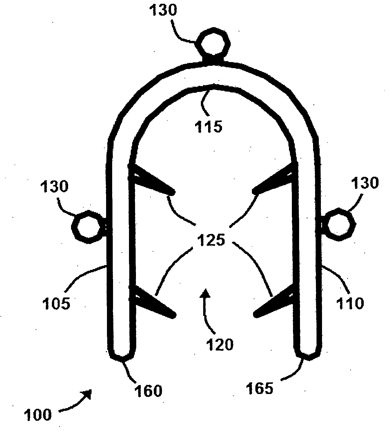
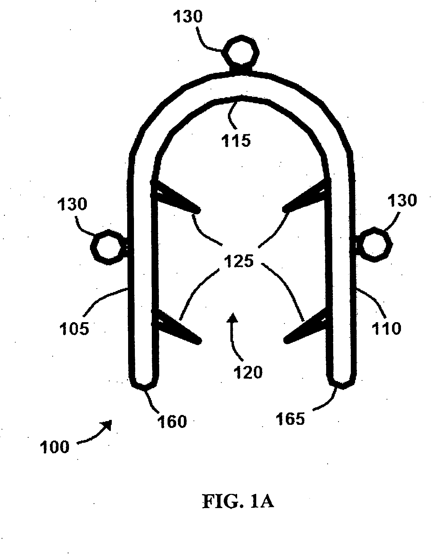
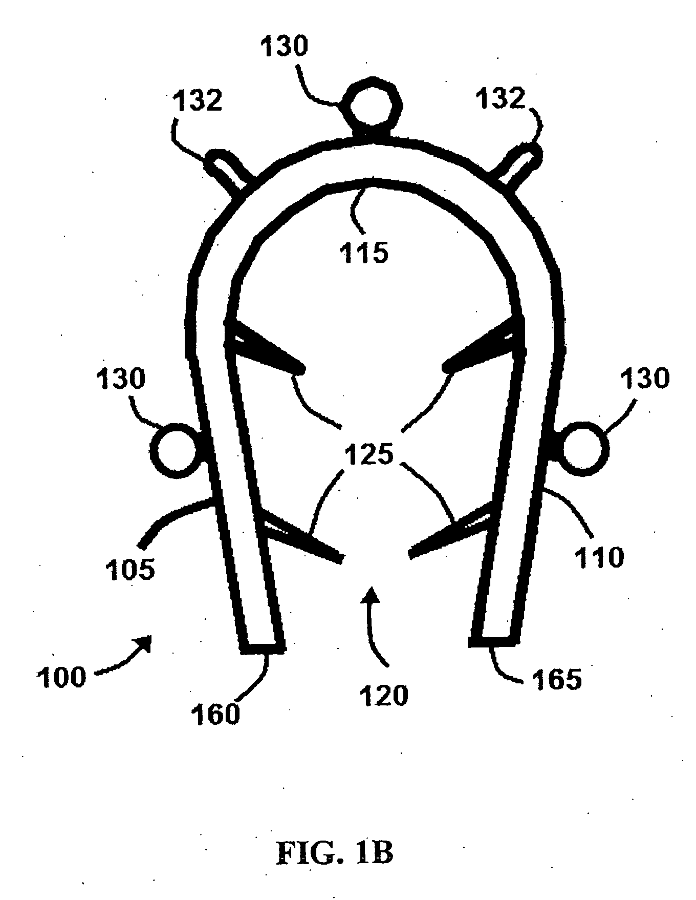
[0104]FIGS. 1A, 1B and 2, illustrate end views and a side view of exemplary embodiments of a clamp 100. Clamp 100 comprises a first side 105, a second side 110, and a coupling portion 115 that couples first side 105 to second side 110. First side 105 and second side 110 comprise end portions 160 and 165, respectively, that are distal from coupling portion 110. Clamp 100 further comprises an open space 120 between first side 105 and second side 110. In the exemplary embodiment shown, first side 105 and second side 110 comprise gripping members 125 and receiving members 130. As shown in FIG. 2, clamp 100 also comprises a first end 145 and a second end 150.

[0105]In certain embodiments, gripping members 125 may be small projections, prongs, tines, tabs, barbs or spikes directed toward open space 120. Gripping members 125 may also be used in combination with cement, epoxy, banding, or small screws in exemplary embodiments. In certain embodiments, gripping members 125 may be formed by def...


PUM


Abstract

Systems, methods, and kits incorporating a clamp for securing to bone tissue. The clamp includes gripping members to secure the clamp to the bone tissue without the use of screws. The clamp may be used to treat spinal conditions, and may be secured to the spinous process of vertebrae. Systems, methods and kits can incorporate a fusion member configured to fuse between adjacent spinous processes.

Description

RELATED APPLICATIONS[0001]This application claims priority to, and incorporates by reference, each of the following applications: U.S. Provisional Patent Application 61 / 017,336 filed Dec. 28, 2007; U.S. Provisional Patent Application 61 / 023,327 filed Jan. 24, 2008; U.S. Provisional Patent Application 61 / 104,199 filed Oct. 9, 2008; and U.S. Provisional Patent Application 61 / 108,368 filed Oct. 24, 2008.BACKGROUND INFORMATION[0002]1. Field of the Invention[0003]Exemplary embodiments of the present disclosure comprise a devices that can be secured to bone tissue and methods of securing the devices. In specific exemplary embodiments, a device may be secured to a spinous process of a vertebra. In other exemplary embodiments, a device may be secured to a calvarial flap or other bone tissue.[0004]2. Description of Related Art[0005]The pedicle screw is a common medical device currently used to attach components to a patient's vertebrae. While providing a stable platform to attach components ...

Claims


Application Information

Patent Timeline
Patent Type & Authority Applications(United States)
IPC IPC(8): A61B17/70A61B17/84A61B17/88
CPCA61B17/688A61B17/7053A61B17/8085A61B17/8061A61B17/8076A61B17/7062A61B17/7067
Inventor GORDON, CHARLESDEATON, JAMES E.
Owner WENZEL SPINE
Why Eureka
Try Eureka