Engine control strategy

a technology of engine control and control strategy, applied in the direction of engines, machines/engines, mechanical equipment, etc., can solve the problems of increasing the fuel consumption and emissions of unburned hydrocarbons, not successfully entering the market place, and reducing the efficiency of scavenging and volumetric efficiency, so as to minimise the short circuit of the intake charge, minimise the pumping loss, and reduce the effect of scalding and volumetric efficiency

Inactive Publication Date: 2009-08-13
ORBITAL ENGINE CO PTY LTD
View PDF6 Cites 3 Cited by
  • Summary
  • Abstract
  • Description
  • Claims
  • Application Information

AI Technical Summary

Benefits of technology

[0025]In prior art applications it has been known to allow a significant degree of overlap between the intake valve open phase and the exhaust valve open phase (commonly referred to as valve overlap). In such prior art cases this overlap can provide benefits in terms of better scavenging and volumetric efficiency as it allows for fluid dynamic effects. Such significant valve overlap can cause some short circuiting of the intake air directly to the exhaust.
[0026]For the present Invention, it is desirable to eliminate, or at least minimise, any short circuiting of the Intake charge to the exhaust. This can be done by ensuring zero overlap between the intake valve open phase and the exhaust valve open phase.
[0027]It has been found that a more preferable arrangement is for there to be a small degree of overlap so that there is no stage during the expansion stroke of the piston that the combustion chamber is completely sealed as this would lead to pumping losses as the piston would continue its expansion stroke against a closed combustion chamber thus creating a negative pressure (also known as “over-expansion”). In such case the degree of valve overlap is controlled to minimise pumping losses.
[0028]Because there is deliberately little opportunity for clearing the exhaust gas from the combustion chamber some exhaust gas is consequently retained in the combustion chamber. Furthermore, less time is available for the fresh intake charge to cool the combustion chamber.
[0029]The presence of retained exhaust gas in the combustion chamber can prove to be useful, as it establishes a higher initial temperature within the combustion chamber at the point of ignition. The retained exhaust gases may also contribute to a reduction in pumping and throttling losses in the induction process, as a reduced volume of air is inducted. The retained exhaust gases also dilute the inducted air, which may assist in operation of the combustion process at stoichiometric conditions.
[0030]It is desirable to operate the engine such that it is only necessary to use a conventional catalytic converter, such as a three-way catalytic converter. This requires that there be stoichiometric operation (which is typically associated with a homogeneous fuel-air charge), avoiding the need for a lean NOx trap (which is required to absorb NOx gases emitted from an engine operating with excess oxygen present in the exhaust gas, as typically arises in cases where a lean fuel-air mixture is employed).

Problems solved by technology

A further problem with an engine operating under the two-stroke cycle is the short-circuiting of fresh charge from the intake port to the exhaust port which increases fuel consumption and emissions of unburned hydrocarbons.
Lean burn engines, however, have not penetrated successfully into the market place, and in fact output volumes are reducing, with many manufacturers replacing their current lean-burn engines with engines that operate at stoichiometric air-fuel ratio.
This is primarily due to the very high cost associated with the after-treatment of the emissions during lean operation.
As well, lean operation has been found to be limited, leading to reduced or even no benefit achieved for many driving conditions, this offering little advantage over the stoichiometric combustion systems currently in production.

Method used


Image

  • Engine control strategy
  • Engine control strategy
  • Engine control strategy

Examples


Embodiment Construction

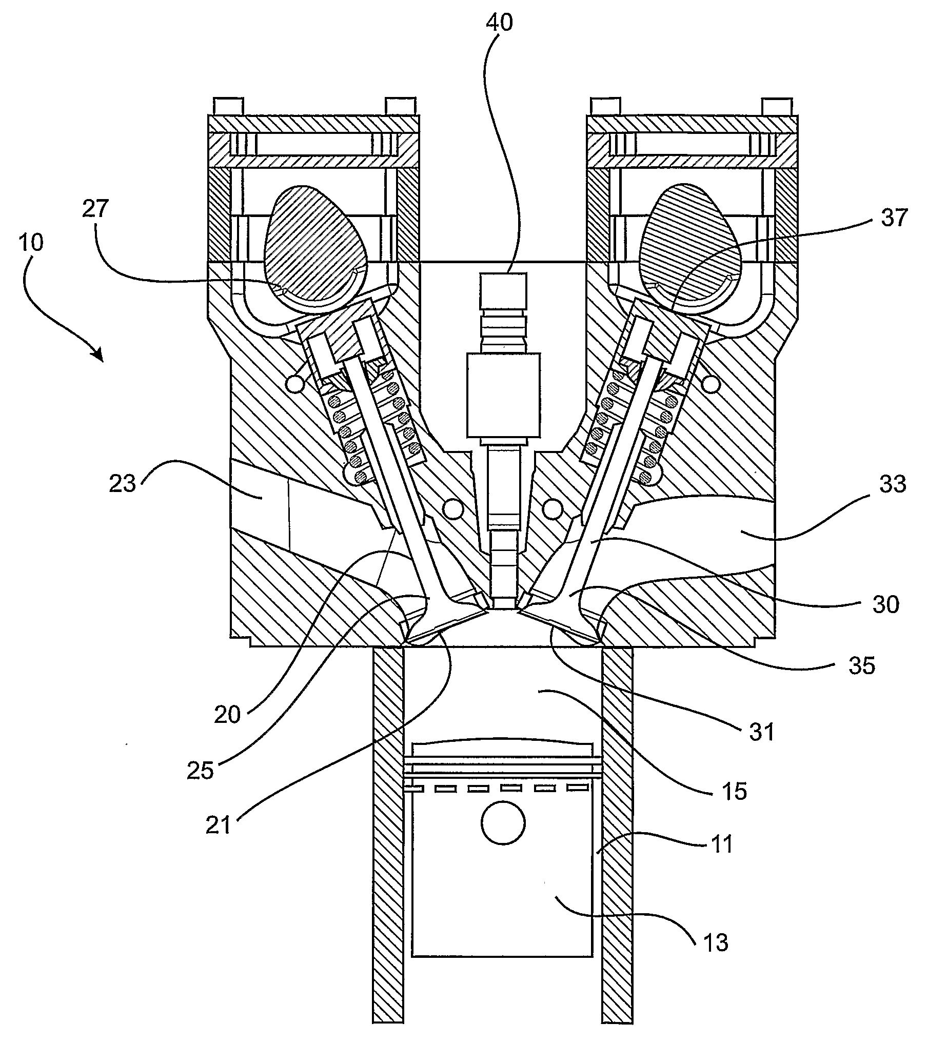
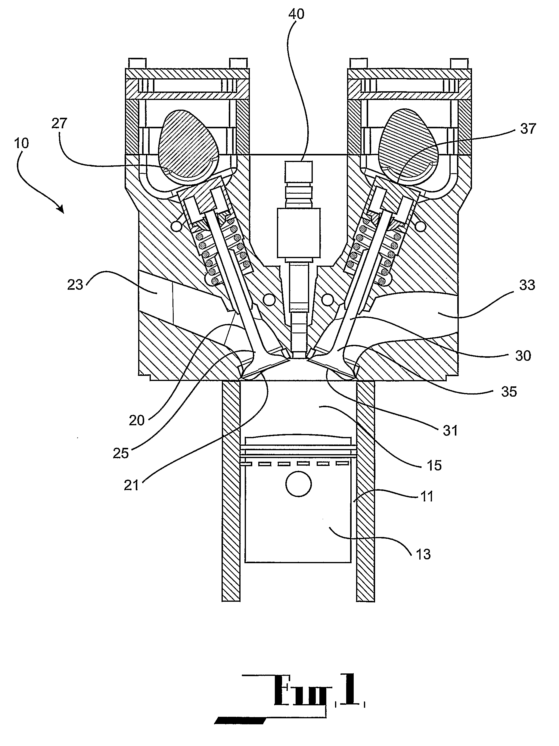
[0050]The embodiment is directed to a reciprocating internal combustion engine 10 which is capable of operating in either two-stroke or four-stroke cycles of operation, with selective switching therebetween.

[0051]The engine 10 comprises a cylinder 11 and a piston 13 accommodated in the cylinder. The cylinder 11 and piston 13 cooperate to define a combustion chamber 15. The combustion chamber 15 undergoes volume expansion and contraction upon reciprocatory movement of the piston 13 within the cylinder 11 between top-dead-centre (TDC) and bottom-dead-centre (BDC) positions.

[0052]An inlet means 20 is provided for introducing an air charge into the combustion chamber and an outlet means 30 is provided for discharging exhaust gas fro in the combustion chamber.

[0053]The inlet means 20 comprises an inlet port 21 opening onto the combustion chamber 15 at the terminal end of a delivery duct 23, and an inlet valve 25 for opening and closing the inlet port 21. A control means 27 is provided fo...


PUM


Abstract

An internal combustion engine (10) has at least one combustion chamber (15) defined by a piston (13) accommodated in a cylinder (11). The method of operating the engine (10) comprises opening an exhaust means (30) as the combustion chamber (15) expands to permit fluid to discharge from the combustion chamber (15), opening an inlet means (20) as the combustion chamber continues to expand to admit the intake air into the combustion chamber (15); closing the exhaust means (30) as the combustion chamber still continues to expand to interrupt discharge of fluid from the combustion chamber (15), and closing the inlet means (20) to interrupt admission of the intake air into the combustion chamber (15). With this operating sequence, scavenging of the combustion chamber (15) is incomplete and so there is a relatively large residual fluid within the combustion chamber.

Description

FIELD OF THE INVENTION[0001]This invention relates to engine control strategies for internal combustion engines. In certain applications, the invention may be applicable to an engine system capable of operating in either two-stroke or four-stroke combustion cycles and switching between the two-stroke and four-stroke combustion cycles.BACKGROUND ART[0002]A reciprocating internal combustion engine operating with a two-stroke combustion cycle may be piston ported or alternatively may have valves controlling the induction and exhaust processes. In the case of piston ported designs, port operation is typically symmetrical about the bottom-dead-centre (BDC) position of the piston; that is, the timing of opening of the inlet port before BDC position is approximately equal to the timing of closing of the inlet port after BDC, and the timing of opening of the exhaust port before BDC is also approximately equal to the timing of opening of the exhaust port after BDC. Typically, there is some o...

Claims


Application Information

Patent Timeline
Patent Type & Authority Applications(United States)
IPC IPC(8): F02B69/06F01N3/10F02B17/00F01L1/34
CPCF02B47/08Y02T10/22Y02T10/121Y02T10/12
Inventor CATHCART, GEOFFREY PAULZUBKO, ALEXANDER
Owner ORBITAL ENGINE CO PTY LTD
Why Eureka
Try Eureka