Tubular threaded joint
a technology of threaded joints and threaded joints, which is applied in the direction of screw threaded joints, hose connections, mechanical equipment, etc., can solve the problems of inability to withstand a large compressive load, leakage, and increase the development of wells in disadvantageous environments such as in the sea or in the polar regions, so as to reduce the tightening force at the time of tightening the threaded joint, the effect of easy tightening operation
- Summary
- Abstract
- Description
- Claims
- Application Information
AI Technical Summary
Benefits of technology
Problems solved by technology
Method used
Image
Examples
example 1
[0095]In order to clearly demonstrate the effects of the present invention, a compressive load was applied to the test members shown in Table 1 by tightening, and deformation of the lip zone was observed.
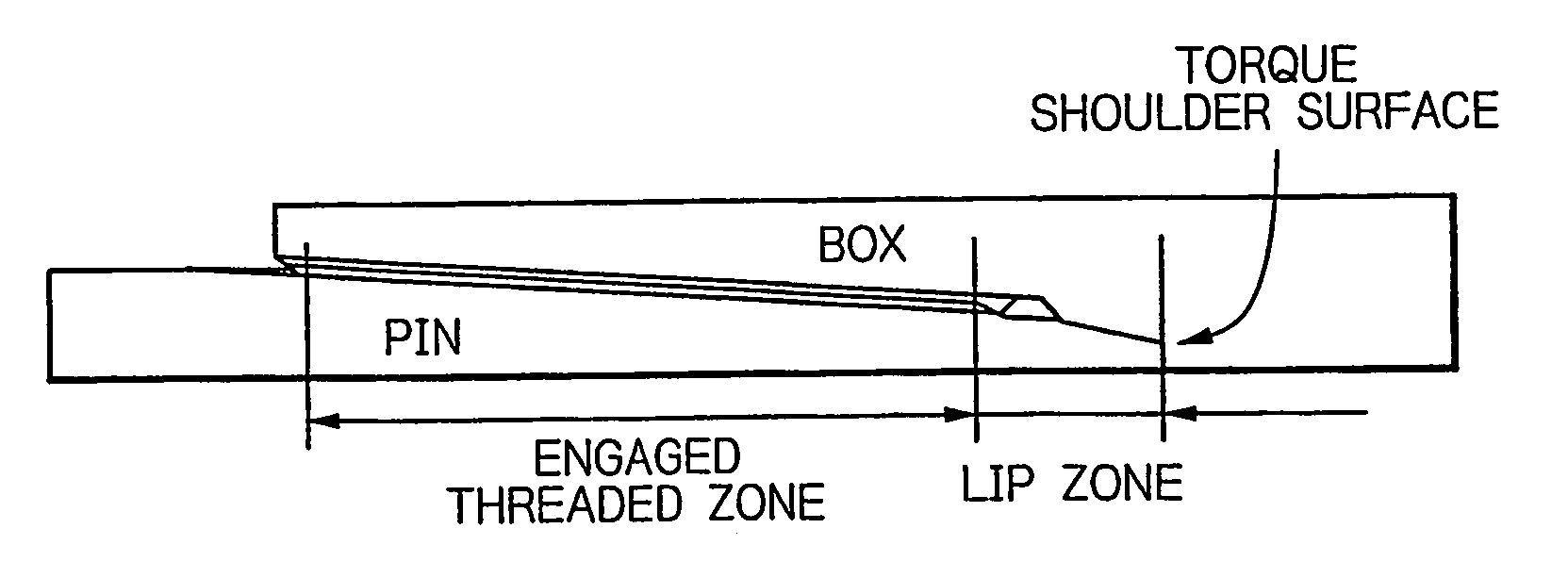
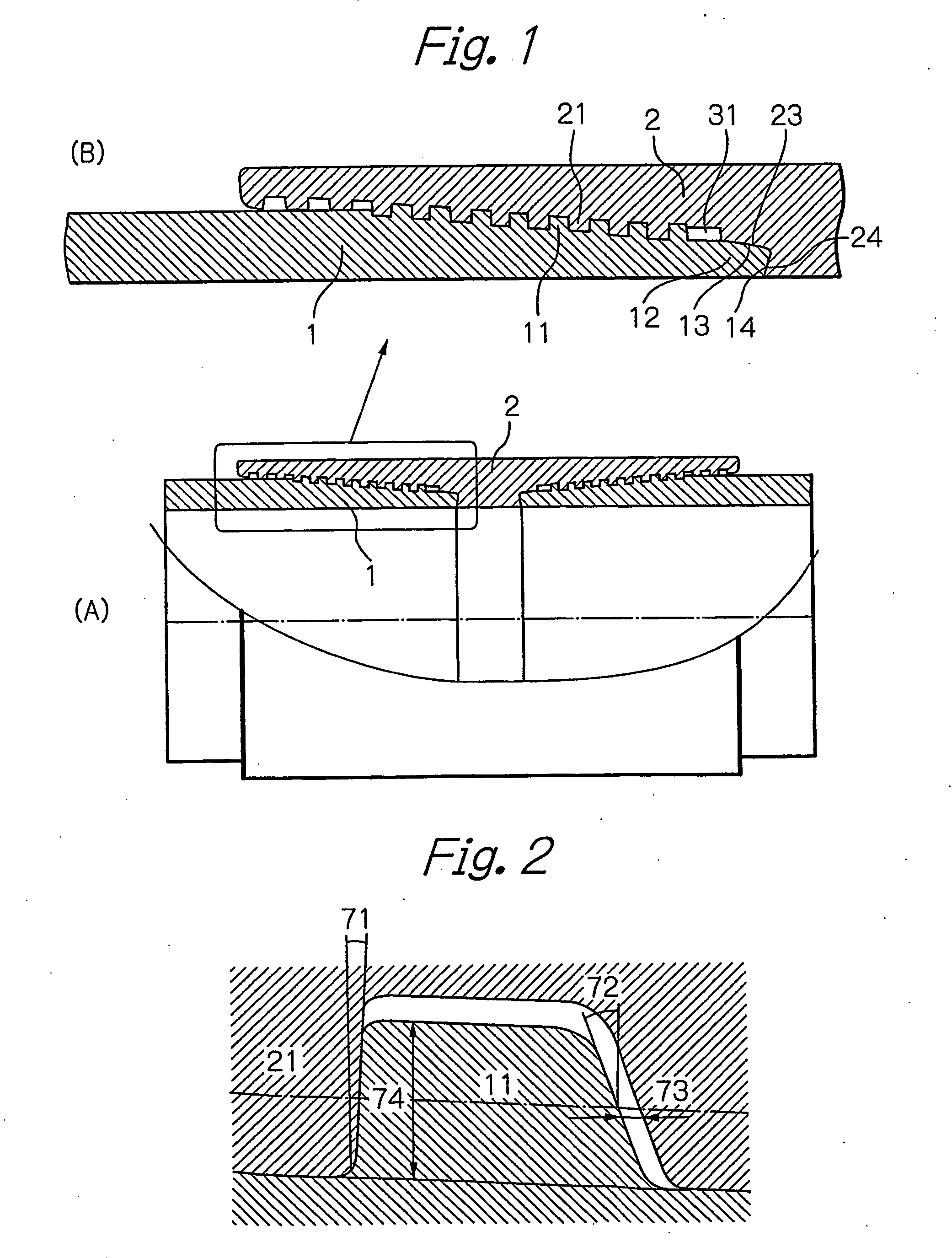
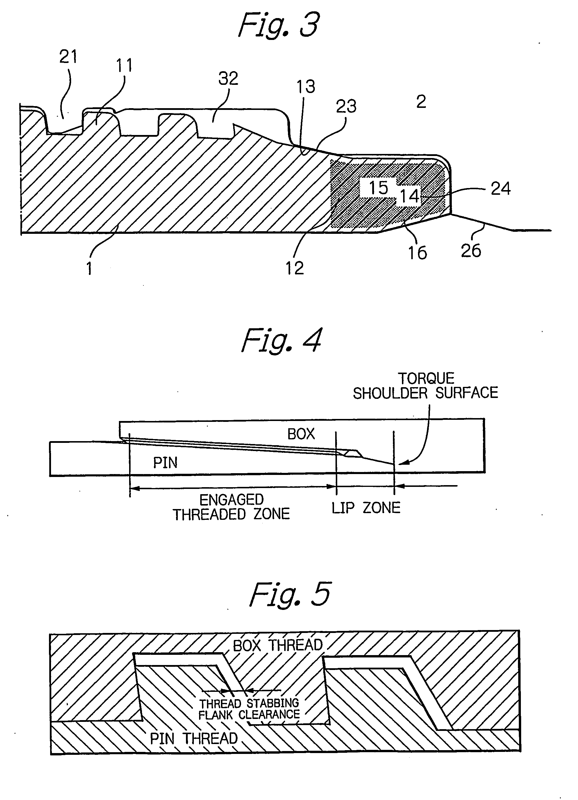
[0096]Each of the test members shown in Table 1 was a threaded joint for oil country tubular goods of the coupling type like that shown in FIG. 3. They were for use with respect to a 9.625″×53.5 (lb / ft) steel pipe (outer diameter of 244.5 mm and wall thickness of 13.84 mm). The steel used for all of the test members was that specified by API specification P110. The shoulder surfaces were an end shoulder surface located at the end of the pin and a corresponding shoulder surface of the box. The lip zone had on its outer periphery a metal-to-metal seal surface (length of 5.5 mm) in the vicinity of the threaded zone and a noncontacting region on the outer end side thereof. In contrast to FIG. 3, there was no unengaged thread on the end portion of the threaded zone.
[0097]The screw thread...
example 2
[0100]An evaluation test was carried out in the same manner as in Example 1, but in this example, the stabbing flank of the male thread of the pin was divided into a first portion on the root side and a second portion on the crest side having different slope angles. In this example, in order to simplify analysis, as shown in FIGS. 6 and 8, the first portion and the second portion of the stabbing flanks were both made conical surfaces (namely, having a longitudinal section along the pipe axis substantially formed by a straight line). The angle of slope of the stabbing flank was 10° for the first portion and 45° for the second portion. The ratio of the lip length to the stabbing flank clearance was 200 (the stabbing flank clearance was 0.1 mm and the lip length was 20 mm). By varying the height of the first portion of the stabbing flank, the ratio of the height of the first portion with respect to the overall thread height (the thread stabbing flank height ratio in Table 2) was varied...
PUM
 Abstract
Description
Claims
Application Information
 - R&D
- Intellectual Property
- Life Sciences
- Materials
- Tech Scout
- Unparalleled Data Quality
- Higher Quality Content
- 60% Fewer Hallucinations
Browse by: Latest US Patents, China's latest patents, Technical Efficacy Thesaurus, Application Domain, Technology Topic, Popular Technical Reports.
© 2025 PatSnap. All rights reserved.Legal|Privacy policy|Modern Slavery Act Transparency Statement|Sitemap|About US| Contact US: help@patsnap.com


