Metallic molded sheet and heat shielding cover

a technology of molded sheet and heat shielding cover, which is applied in the direction of manufacturing tools, machines/engines, transportation and packaging, etc., can solve the problems of large volume, large volume, and large volume of molded sheet, and achieves the effect of reducing the number of molded sheets

Inactive Publication Date: 2009-08-13
NICHIAS CORP
View PDF13 Cites 23 Cited by
  • Summary
  • Abstract
  • Description
  • Claims
  • Application Information

AI Technical Summary

Benefits of technology

[0008]Accordingly, an object of the invention is to provide a metallic molded sheet which is suitable as a heat shielding cover and which has moldability into a complex shape, has light weight and sufficient shape retainability, has high reliability against fracture and the like in a high-load environment, and is free of cracks and breakage during molding.
[0022]According to the invention, it is possible to obtain a metallic molded sheet having a corrugated surface in which two kinds of waveforms each having a sinusoidal cross section perpendicularly intersect each other without forming bent portions at the portions where the two kinds of waveforms perpendicularly intersect each other. In addition, it is possible to maintain the thickness of the starting metal sheet as it is over the entire surface, and the metallic molded sheet has high strength, has no unevenness in strength, and is free of the occurrence of cracks or pinholes during molding. For this reason, even if this metallic molded sheet is disposed by being molded into an arbitrary shape as a heat shielding cover, cracks do not occur at the portions where the two kinds of waveforms perpendicularly intersect each other, and the durability thereof becomes excellent. In addition, since reentrant side walls are absent, fracture at the time of unbending is difficult to occur, so that the durability is high in a vibratory environment. Furthermore, since ridges are formed by bending, it is possible to obtain performance equivalent to that of deep drawability based on unbending.

Problems solved by technology

Further, since these heat shielding covers are in many cases provided in narrow and extensive ranges in the vicinities of the high-temperature exhaust system parts, they often tend to be such complex and large-sized covers as to conform to the shape of matching members.
In addition, control of CO2, which has its inception in the issue of global warming in recent years, is an important challenge, and, for automobiles, individual parts are required to be more lightweight.
However, large-sized heat shielding covers weigh as much as several tens of kilograms, and fixing portions for supporting them are also required to have strength and durability, so that tendencies toward greater size and heavier weight are naturally underway, which is contrary to the tendency toward lighter weight.
In addition, even in sheets which excel in elongation such as steel sheets, low-length portions are partially present in deep drawing which is accompanied by reduced sheet thickness, and stress-concentrated portions where fracture can occur during deep drawing forming or which can be a cause of fracture are inherent.
Hence, there are frequent defects in which these stress-concentrated portions lead to breakage in high-load environments (high temperature, high vibration, salt damage environment, long-time assurance, etc.) as in automobiles.
As long as a steel sheet having an elongation rate of several tens of percent is used, the case would be different, but in the case of an aluminum sheet several percent to ten-odd percent is a limit of its elongation rate, and it is difficult to say that sufficient deep drawability can be ensured.
Furthermore, as for the protruding portions, the sheet thickness becomes thinner than the planar portions, so that the strength is low, and there are cases where cracks, pinholes, or the like are produced during the shape forming.
Since a metal sheet is ordinarily work hardened during machining such as side wall forming by strike bending, and the aluminum sheet or the like, in particular, has a small elongation rate, there is a possibility that the bent portion becomes fractured due to the inverse bending force loaded on the reentrant side wall, and it is apprehended that this fractured portion may become a flaw in a vibrational environment, and a very small fracture may progress and lead to the breakage of the cover.
In addition, there are cases where a crack occurs along the ridge during molding.

Method used


Image

  • Metallic molded sheet and heat shielding cover
  • Metallic molded sheet and heat shielding cover
  • Metallic molded sheet and heat shielding cover

Examples


example 1

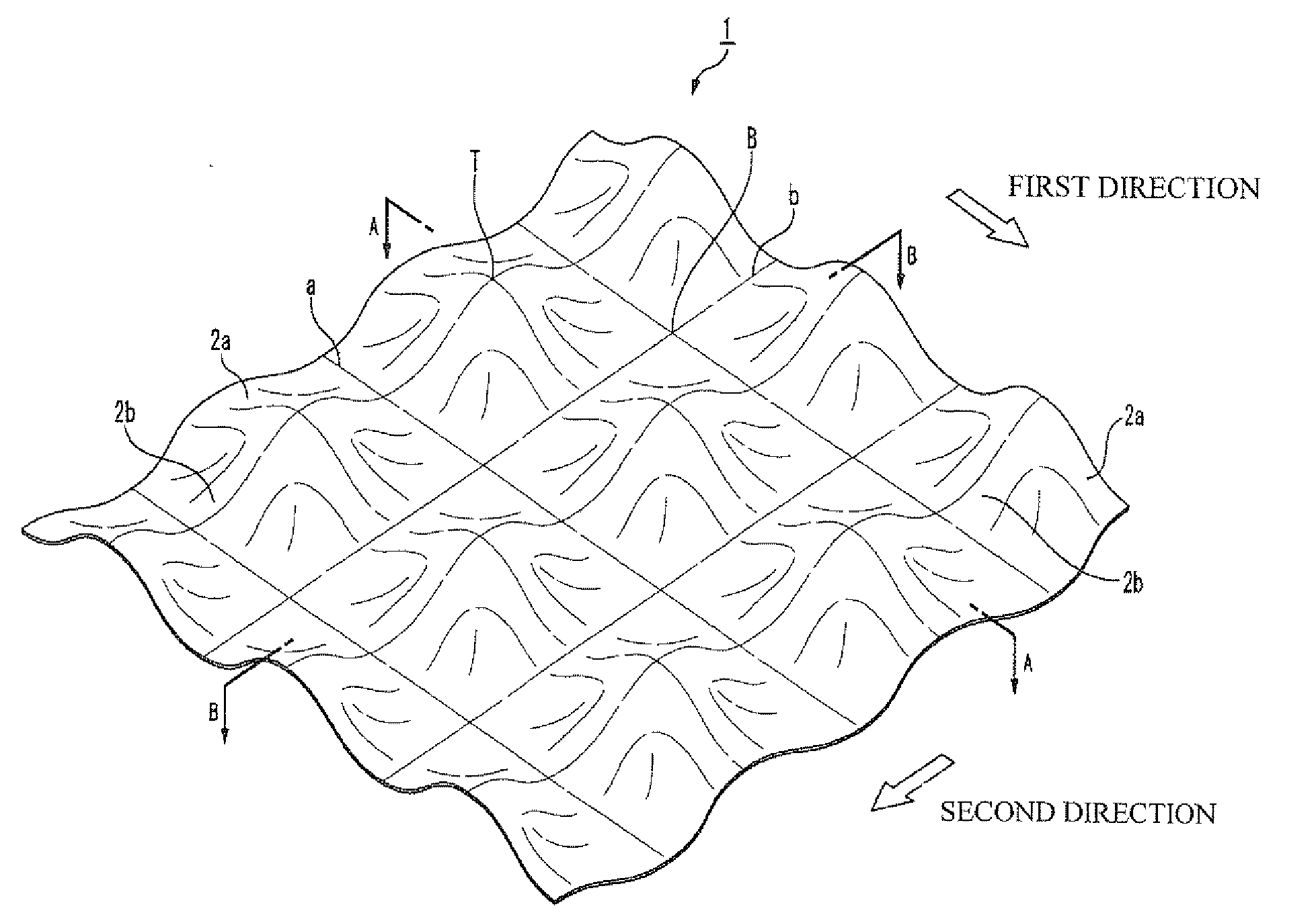
[0048]A specimen with sides each measuring 250 mm was cut out from a 1050 aluminum alloy sheet with a sheet thickness of 0.4 mm, and was passed between the pair of first corrugating rolls having a wave height of 2.8 mm, an interval between crests (pitch) of 6.0 mm, and a gap between upper and lower rolls (D) of 1.5 mm. Then, the specimen having the first waveforms formed therein was passed between the pair of second corrugating rolls having the same teeth profile as the first corrugating rolls and a gap between upper and lower rolls (D) of 1.0 mm, in such a way that the ridge lines of the first waveforms perpendicularly intersected ridge lines of the teeth, to thereby allow the second waveforms to cross over the first waveforms and form the corrugated surface shown in FIG. 1.

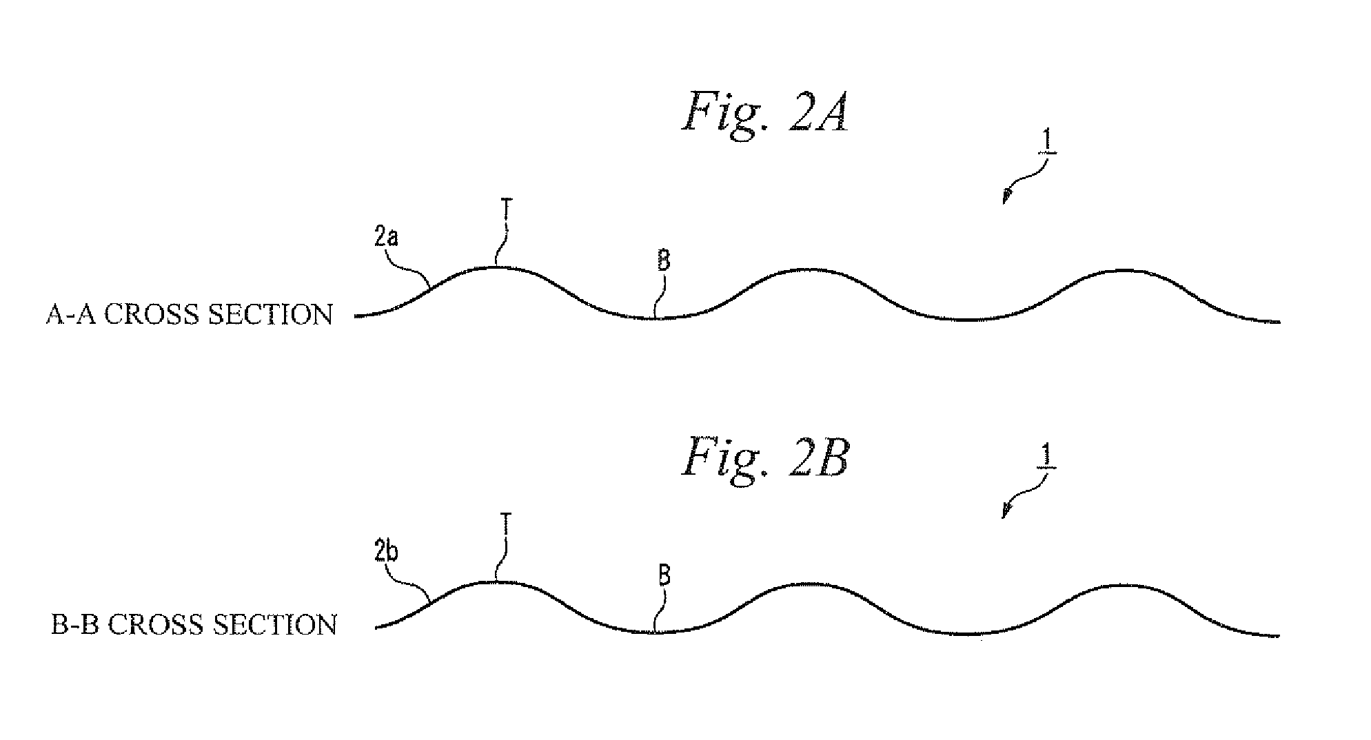
[0049]Observations were made of a cross section (see A-A cross section in FIG. 2A), taken along a ridge line formed by the insertion between the first corrugating rolls, of the specimen with the corrugated surfa...


PUM

PropertyMeasurementUnit
temperaturesaaaaaaaaaa
heightaaaaaaaaaa
heightaaaaaaaaaa

Abstract

The present invention relates to a metallic molded sheet including a metallic sheet having first ridges continuously formed along a first direction and second ridges continuously formed along a second direction which is perpendicular to the first direction, in which the metallic molded sheet has cross-sectional shapes along the first direction and the second direction, each having an identical thickness and continuing sinusoidally, and the metallic molded sheet has a planar shape being a corrugated surface in which ridge lines of first waveforms along the first direction and ridge lines of second waveforms along the second direction perpendicularly intersect each other.

Description

FIELD OF THE INVENTION[0001]The present invention relates to a metallic molded sheet which has corrugated irregularities formed therein and is suitable as a shielding cover which is disposed on a heat generating portion of such as a household electrical appliance, or an exhaust pipe, an engine, or the like of an automobile.BACKGROUND OF THE INVENTION[0002]Since an automobile during engine operation produces exhaust gases at high temperatures of 900° C. or more, exhaust system parts, such as an exhaust manifold, a catalyst system, pipes, a muffler, and the like undergo high temperatures. Therefore, a large number of heat shielding covers are provided in their peripheries for the purposes of prevention of thermal damage and prevention of burn injury. Further, since these heat shielding covers are in many cases provided in narrow and extensive ranges in the vicinities of the high-temperature exhaust system parts, they often tend to be such complex and large-sized covers as to conform t...

Claims


Application Information

Patent Timeline
Patent Type & Authority Applications(United States)
IPC IPC(8): B32B3/28F01N7/08B21B39/20F01N13/08F01N13/14
CPCY10T428/12417B21D13/04B21B1/227
Inventor HIRAOKA, AKINAOKONDOH, MOTONORIKATO, TADAKATSUNIWA, TAKAHIRO
Owner NICHIAS CORP
Why Eureka
Try Eureka