Control apparatus for vehicular power transmitting system

a control apparatus and transmission system technology, applied in the direction of dynamo-electric gear control, gear control, instruments, etc., can solve the problem that the control apparatus disclosed in the publication is not configured to ensure a high degree of control respons

Active Publication Date: 2009-08-13
TOYOTA JIDOSHA KK
View PDF7 Cites 36 Cited by
  • Summary
  • Abstract
  • Description
  • Claims
  • Application Information

AI Technical Summary

Benefits of technology

[0027]In the above-described mode (7) of the present invention, the vehicular power transmitting system can provide a drive fo

Problems solved by technology

Namely, the control apparatus disclosed in the publication is not configured to assure a high degree of control

Method used


Image

  • Control apparatus for vehicular power transmitting system
  • Control apparatus for vehicular power transmitting system
  • Control apparatus for vehicular power transmitting system

Examples


Embodiment Construction

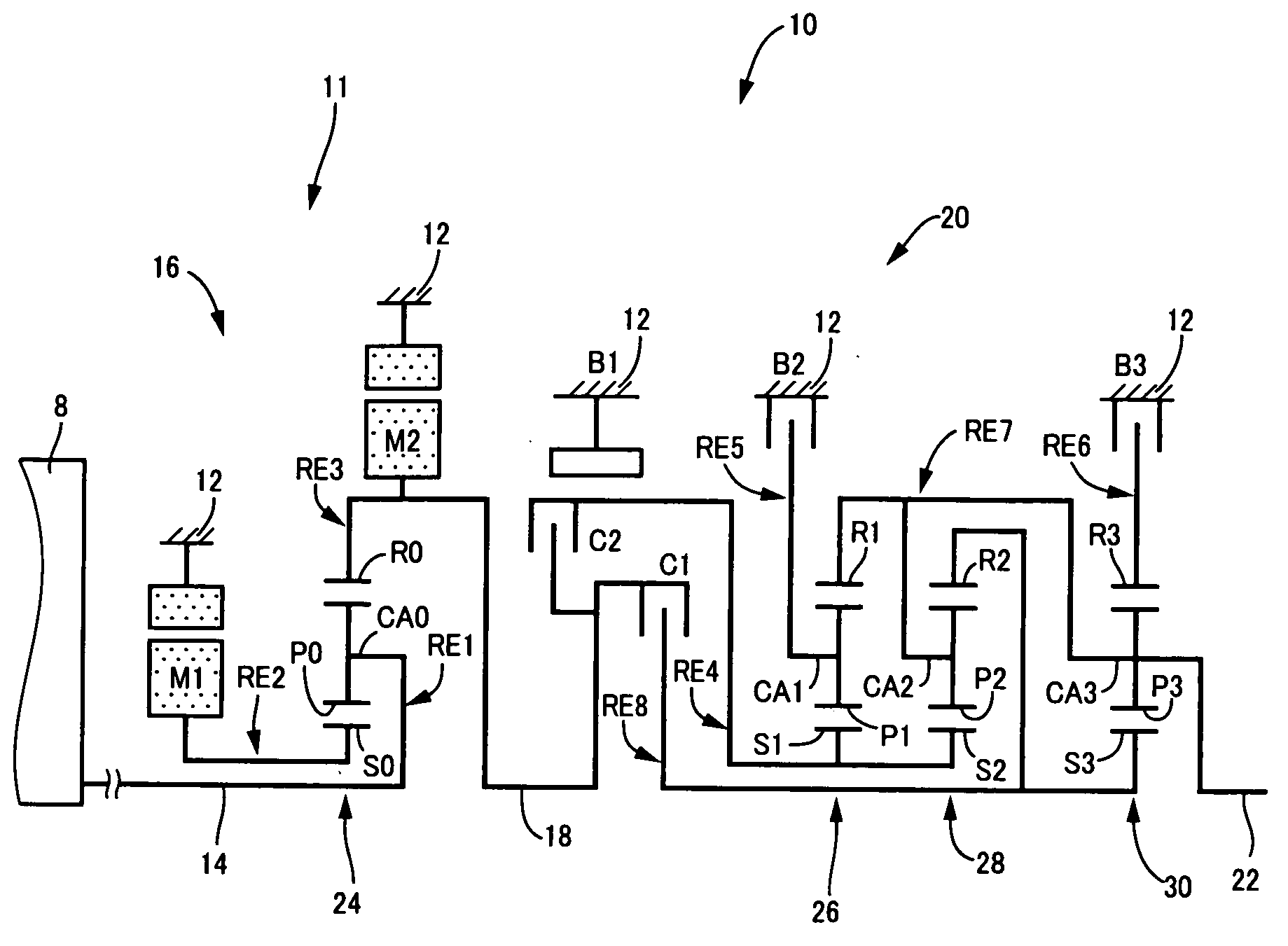
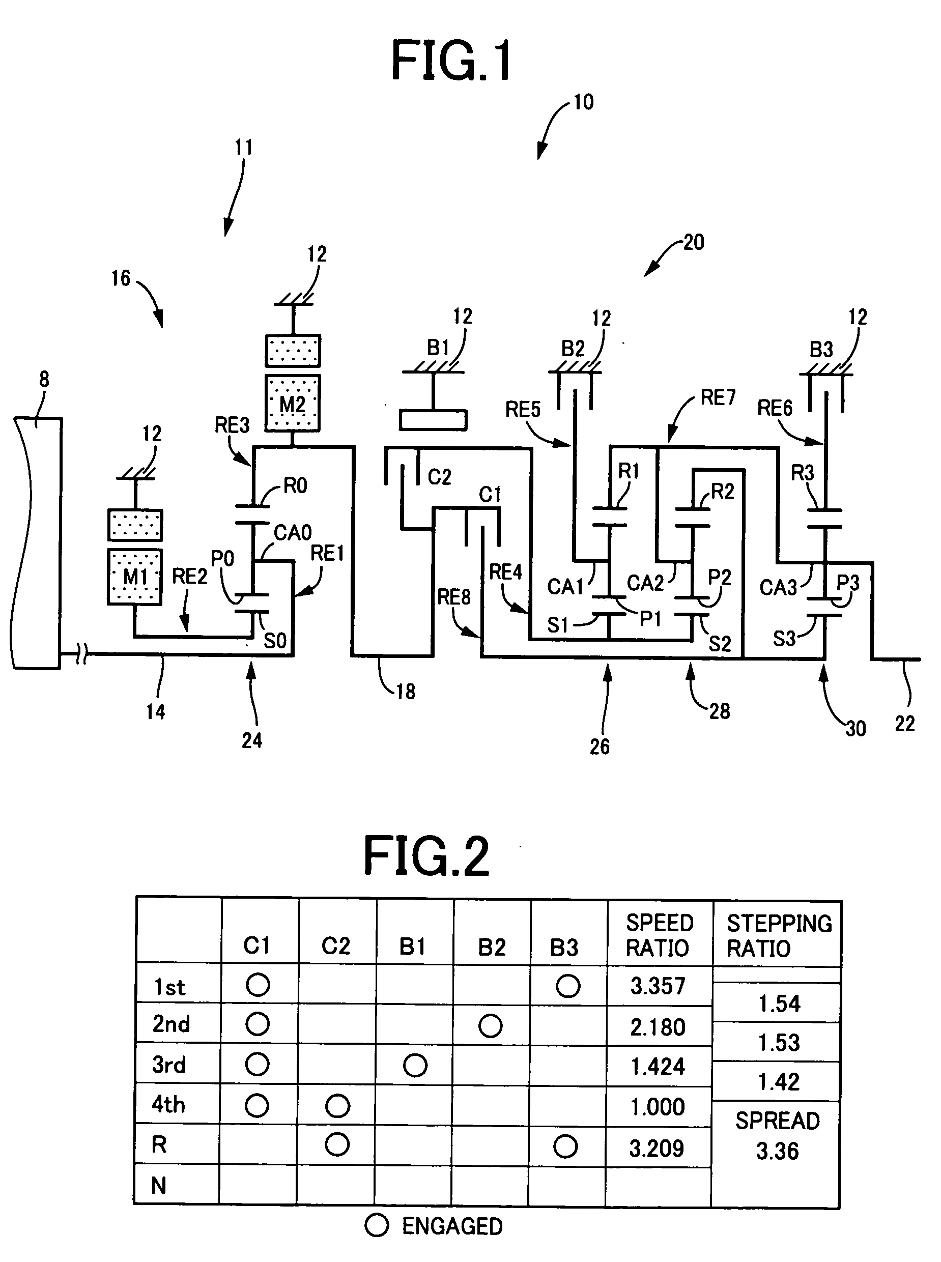
[0042]Referring first to the schematic view of FIG. 1, there is shown a power transmitting system 10 for a hybrid vehicle, which is controlled by a control apparatus constructed according to one embodiment of this invention. As shown in FIG. 1, the power transmitting system 10 includes: an input rotary member in the form of an input shaft 14; a continuously-variable transmission portion in the form of a differential portion 11 connected to the input shaft 14 either directly, or indirectly via a pulsation absorbing damper (vibration damping device) not shown; a power transmitting portion in the form of an automatic transmission portion 20 disposed between the differential portion 11 and drive wheels 34 (shown in FIG. 7) of the hybrid vehicle, and connected in series via a power transmitting member 18 (power transmitting shaft) to the differential portion 11 and the drive wheels 34; and an output rotary member in the form of an output shaft 22 connected to the automatic transmission p...


PUM


Abstract

A control apparatus for a vehicular power transmitting system including an electrically controlled differential portion having an electric motor, and an automatic transmission portion, the control apparatus including shift control portion operable upon determination that a jump shift-down action of the automatic transmission portion directly to a target gear position while skipping at least one intermediate gear position should take place and upon inhibition of the jump shift-down action, to generate a shifting command to perform the jump shift-down action when total jump-shift-down-action time required for the jump shift-down action is shorter than total sequential-shift-down-operation time required for a sequential shift-down operation consisting of a shift-down action to each intermediate gear position and a shift-down action from the last intermediate gear position to the target gear position, and a shifting command to perform the sequential shift-down operation when the total jump-shift-down-action time is not shorter than the total sequential-shift-down-operation time.

Description


Claims


Application Information

Patent Timeline
IPC IPC(8): F16H59/14F16H48/20B60K6/445B60K6/547B60L50/16B60W10/08B60W10/10B60W20/00F16H3/72F16H59/42F16H59/74F16H61/02F16H61/04F16H61/16F16H61/68F16H61/684F16H61/686
CPCB60K1/02Y10T477/33B60K6/445B60K6/547B60L2240/441B60L2240/445B60L2240/486B60W10/06B60W10/08B60W10/115B60W20/00B60W2510/0638B60W2510/0676B60W2510/068B60W2510/0685B60W2510/1005B60W2510/1075B60W2510/244B60W2520/10B60W2520/105B60W2520/28B60W2530/10B60W2540/10B60W2540/12B60W2710/0605B60W2710/0616F16H3/728F16H61/0213F16H61/16F16H2061/0444Y02T10/6286Y02T10/6239Y10S903/945B60Y2400/435Y10T477/6936B60K6/365Y02T10/62B60W20/10
Inventor NOHARA, HIDEHARUSUZUKI, TOSHINARI
Owner TOYOTA JIDOSHA KK
Why Eureka
Try Eureka