
Circuit Module

a circuit module and circuit technology, applied in the field of circuit modules, can solve the problems of limited service life and weak signal that can thereby be read out, and achieve the effects of high integration density, not overly complex, and excellent environmental compatibility

Active Publication Date: 2009-08-20
ROBERT BOSCH GMBH
View PDF7 Cites 15 Cited by
  • Summary
  • Abstract
  • Description
  • Claims
  • Application Information

AI Technical Summary

Benefits of technology

[0006]In accordance with an example embodiment of the present invention, the piezoelement is supported on the substrate, it being clamped in clamping regions and capable of executing a free oscillatory motion by at least one other freely oscillating region. In accordance with one especially preferred specific embodiment, the piezoelement is clamped between two substrate elements, in particular two substrate halves; the substrate halves form a cavity therebetween within which the piezoelement is able to freely oscillate without being mechanically damaged. The depth and shape of the cavity allows it to function as overload stops to limit oscillatory motion or deflection, a stop arrangement being optionally provided as well for this purpose.
[0013]The present invention provides an autonomous circuit module, in particular sensor module, which features a long service life, minimal disposal problems, respectively excellent environmental compatibility, a design that is not overly complex, and a high integration density. Because the piezoelement is clamped between the substrate halves that are already used for accommodating the components and, optionally, for external shielding, few additional auxiliary devices are required.
[0014]Thus, the circuit module according to the present invention may be used wherever regular or irregular mechanical loads occur. This is possible, in particular, for a use as a tire sensor module, which may be introduced, for example, vulcanized or bonded directly into the rubber material of the tire, for example in the area of the tread, or be held or clamped in a pocket, and, thus, is able to measure the occurring accelerations more efficiently than in the area of the wheel rim, for example.

Problems solved by technology

An autonomous, battery-based energy supply raises environmental concerns, particularly because of high disposal costs and the outlay entailed in separation processes during disassembly.
Tire sensor modules of this kind are typically mounted on the tire rim since the galvanic cells used as batteries must be disposed of separately from the rubber tire material and since they do not tolerate the temperatures that occur in the tire during vulcanization.
In addition, the service life is limited by the capacity of the battery which often is not replaceable; since the sensor module is limited in size, the batteries should not be dimensioned to be too large.
When current is supplied by electromagnetic radiation, respectively, incoupling, in principle, a passive transponder is formed; however, the signal that can thereby be read out is weak.

Method used


Image

  • Circuit Module
  • Circuit Module
  • Circuit Module

Examples


Embodiment Construction

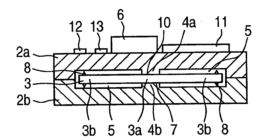
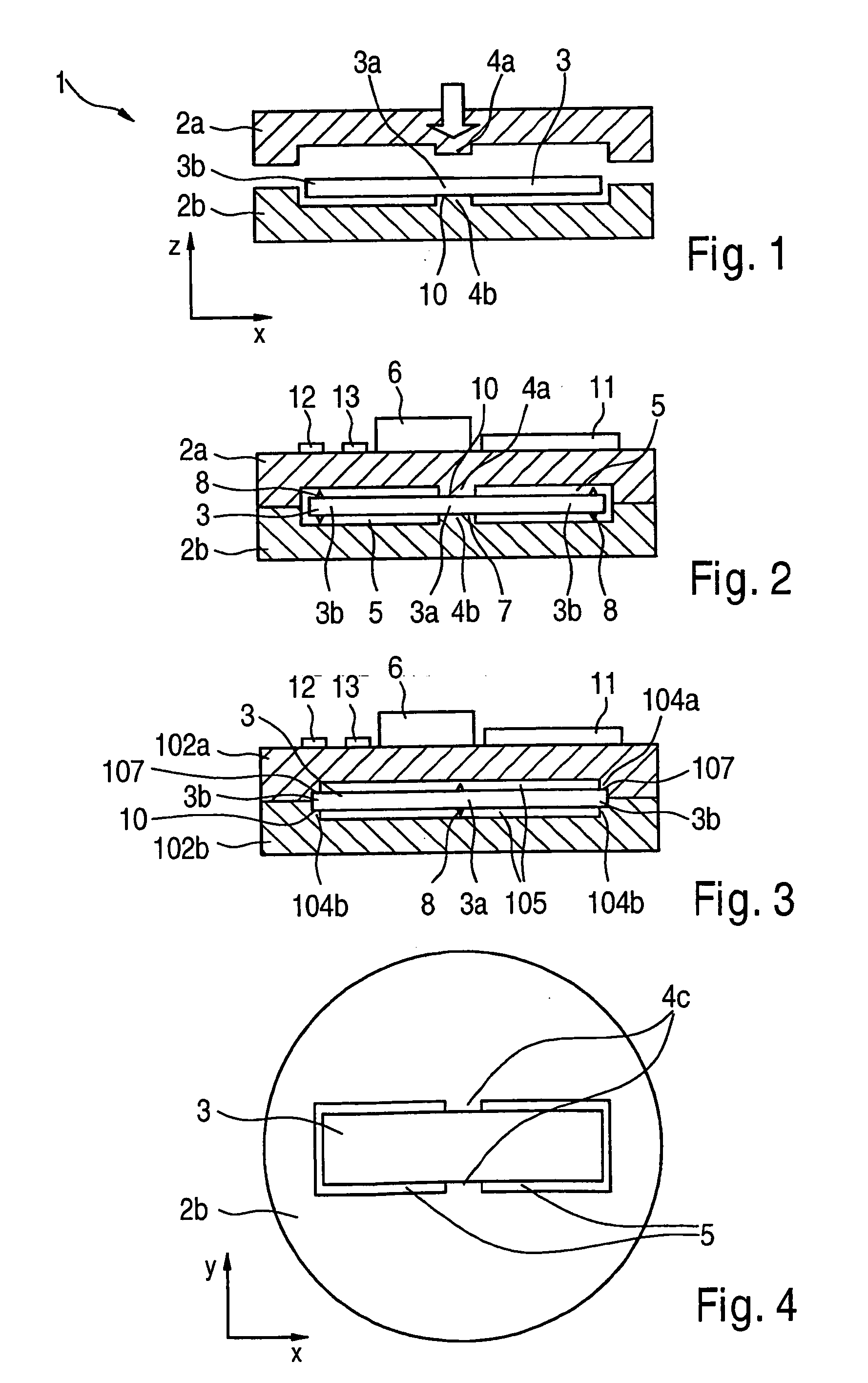
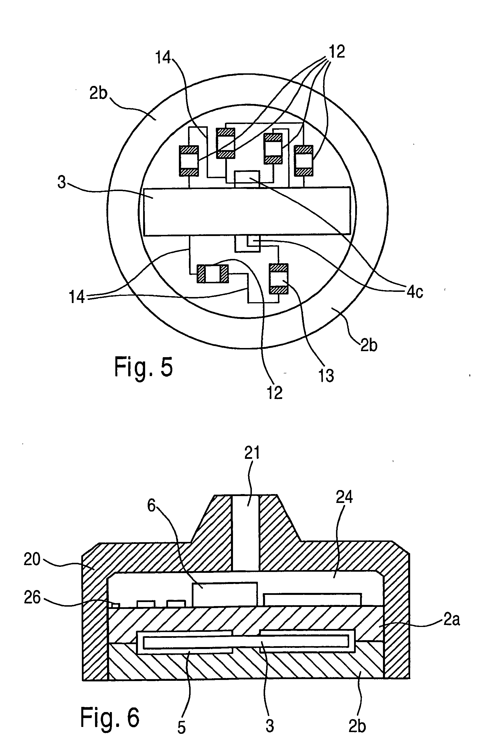
[0022]A circuit module 1 according to the present invention shown in FIG. 2 is composed of at least two substrate halves 2a and 2b and of a piezoelement 3 of a ceramic material that is fastened therebetween. Active or passive components 6, 11, 12, 13 are accommodated on at least one of substrate halves 2a, 2b in a generally known manner.

[0023]In accordance with an example embodiment of the present invention, piezoelement 3 is clamped at one or a plurality of locations. FIG. 1, 2 show a specific embodiment where, as clamping region 3a, a middle region 3a of piezoelement 3 is clamped by two mutually opposing clamping regions 4a, 4b, in the form of projections, of substrate halves 2a, 2b in the Z direction by the formation of a clamp-type connection 7, one continuous or two separate cavities 5 extending in the x direction being formed between substrate halves 2a and 2b, within which cavities outer ends 3b of piezoelement 3 are able to oscillate in the xz plane as oscillatory regions 3b...


PUM


Abstract

A circuit module, in particular a tire sensor module, which at least includes: a substrate, on or in which at least one component is mounted, a piezoelement, which has at least one clamping region and at least one oscillatory region, the piezoelement being clamped in its clamping region on the substrate or on an arrangement secured to the substrate, and its oscillatory region being accommodated in a manner that permits oscillation, contacts provided on the piezoelement for tapping off a piezoelectric voltage, and a current-supply circuit, which receives the piezoelectric voltage generated by the piezoelement, being used as a voltage source for supplying power to the circuit module. The piezoelement is preferably clamped between at least two substrate elements, at least one cavity being formed within which the at least one oscillatory region of the piezoelement is accommodated in a manner that permits deflection, and is limited in its oscillation displacement.

Description

FIELD OF THE INVENTION[0001]The present invention relates to a circuit module that can be used, in particular, as a tire sensor.BACKGROUND INFORMATION[0002]Tire sensors are used, in particular, for measuring internal tire pressure (tire pressure monitoring system, TPMS), as well as the temperature or accelerations which occur inside of the tire. In this connection, a sensor module typically includes a circuit substrate, at least one sensor component, and an antenna via which data are transmitted to a transceiver on the vehicle. Two types of conventional systems supply power. In one system, the energy is supplied by a battery or a galvanic cell, and, in the other, by electromagnetic radiation or incoupling.[0003]An autonomous, battery-based energy supply raises environmental concerns, particularly because of high disposal costs and the outlay entailed in separation processes during disassembly. Tire sensor modules of this kind are typically mounted on the tire rim since the galvanic ...

Claims


Application Information

Patent Timeline
Patent Type & Authority Applications(United States)
IPC IPC(8): B60C23/04H02N2/18
CPCB60C23/0411H02N2/18G01L9/0022
Inventor BUCK, THOMASREICHENBACH, RALF
Owner ROBERT BOSCH GMBH
Learn More