Variable Speed Wind Turbine Configured For Wind Farm Operation

a variable speed, wind turbine technology, applied in the direction of motors, engine control, optimising machine performance, etc., can solve the problems of increasing rotor heating, overexcitation of generators, and underexcitation, and achieve the effect of reducing the effect of low voltage faults and precise control of individual stators

Inactive Publication Date: 2009-08-20
VESTAS WIND SYST AS
View PDF7 Cites 101 Cited by
  • Summary
  • Abstract
  • Description
  • Claims
  • Application Information

AI Technical Summary

Benefits of technology

[0031]The present invention therefore discloses a variable speed wind turbine, and a method for operating such a variable speed wind turbine, adapted for use in a wind farm environment. The variable speed wind turbine includes a DFIG providing power from its stator to a utility grid without undergoing power transformations and back-to-back inverters for processing and otherwise controlling power to and from the DFIG rotor. The present invention also includes a DC link for isolating the back-to-back inverters, scalar control to provide more precise control of individual stator electrical quantities fed to the power grid; and subsystems to ameliorate the effects of low voltage faults.

Problems solved by technology

When excess current is applied to the rotor, the generator is considered to be overexcited.
If the generator receives too little rotor current, it is considered to be underexcited.
Rotor heating is also due to rotor core losses from excitation flux.
Any increases in rotor current to increase reactive power generation therefore increases rotor heating.
In doubly fed induction generators, there are therefore power output limited mandated by heating considerations.
Although absorption of reactive power does not increase rotor heating above what would be experienced by delivery of only real power, the increase in flux due to absorption of reactive power causes excess heating of end sections of a generator's stator.
Therefore, there are also power output limits of DFIG systems due to stator end heating.
However, with FOC, otherwise useful information regarding the AC current in each phase is lost in the transformation process.
Because in certain instances the AC signals are asymmetrical (that is, not equal), useful AC information may be lost during the transformation AC signals from the stationary frame into a rotating frame.
As a consequence, FOC is unable to be used in a system that independently controls the electrical quantities (e.g., voltage, current) of each phase of the power grid.
However, the electrical quantities on each phase of a wind turbine generator may vary due to transients on the grid which may cause uneven thermal stress, unbalanced mechanical forces and high DC link voltages.
Staying connected during fault conditions can have adverse consequences to mechanical components as well.
If power load on a wind turbine is reduced, as it is in a low voltage fault condition, the blades of the turbine could accelerate and damage may occur.
Stated differently, as the wind speed increases, the rotational speed of the generator increases and brings it closer to the upper speed limit of the rotor and generator, and therefore it is not possible to operate a wind turbine at its optimum blade tip-wind speed ratio over the whole wind speed range.

Method used


Image

  • Variable Speed Wind Turbine Configured For Wind Farm Operation
  • Variable Speed Wind Turbine Configured For Wind Farm Operation
  • Variable Speed Wind Turbine Configured For Wind Farm Operation

Examples


Embodiment Construction

[0048]Reference will now be made in detail to embodiments of the invention, examples of which are illustrated in the accompanying drawings. Wherever possible, the same reference numbers will be used throughout the drawings to refer to the same or like parts.

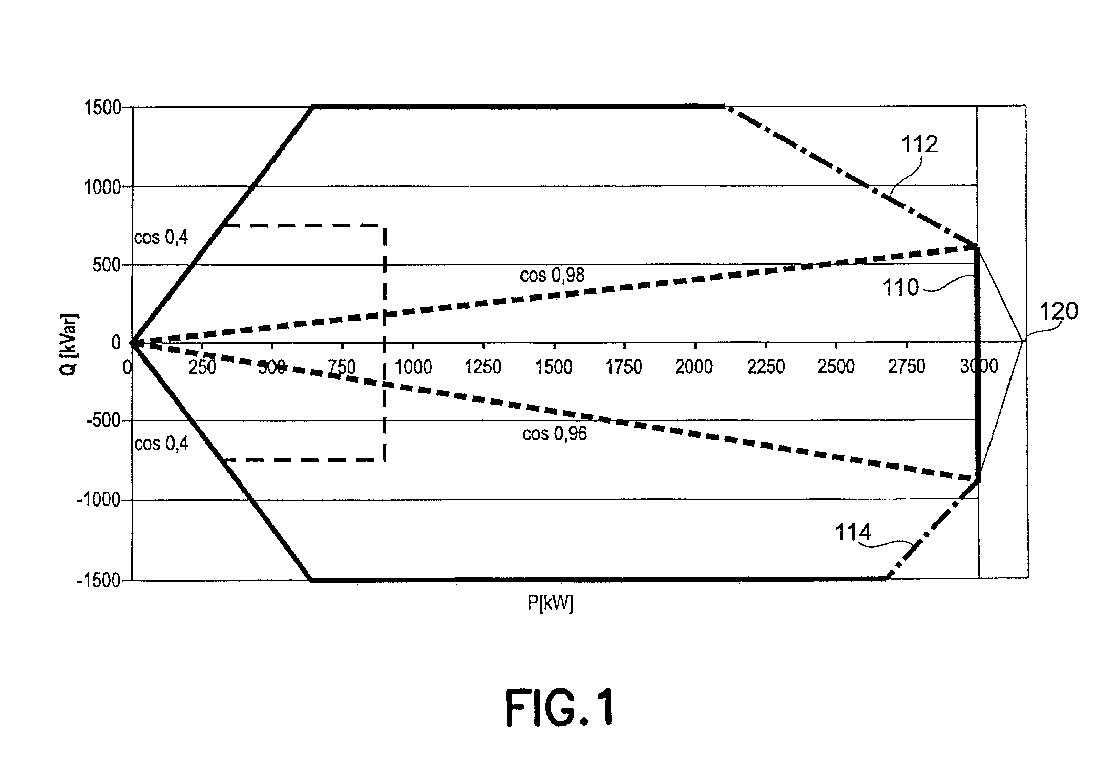
[0049]FIG. 1 describes power output limits of a known DFIG, with line 112 showing the output limits due to rotor heating and line 114 showing stator end heating.

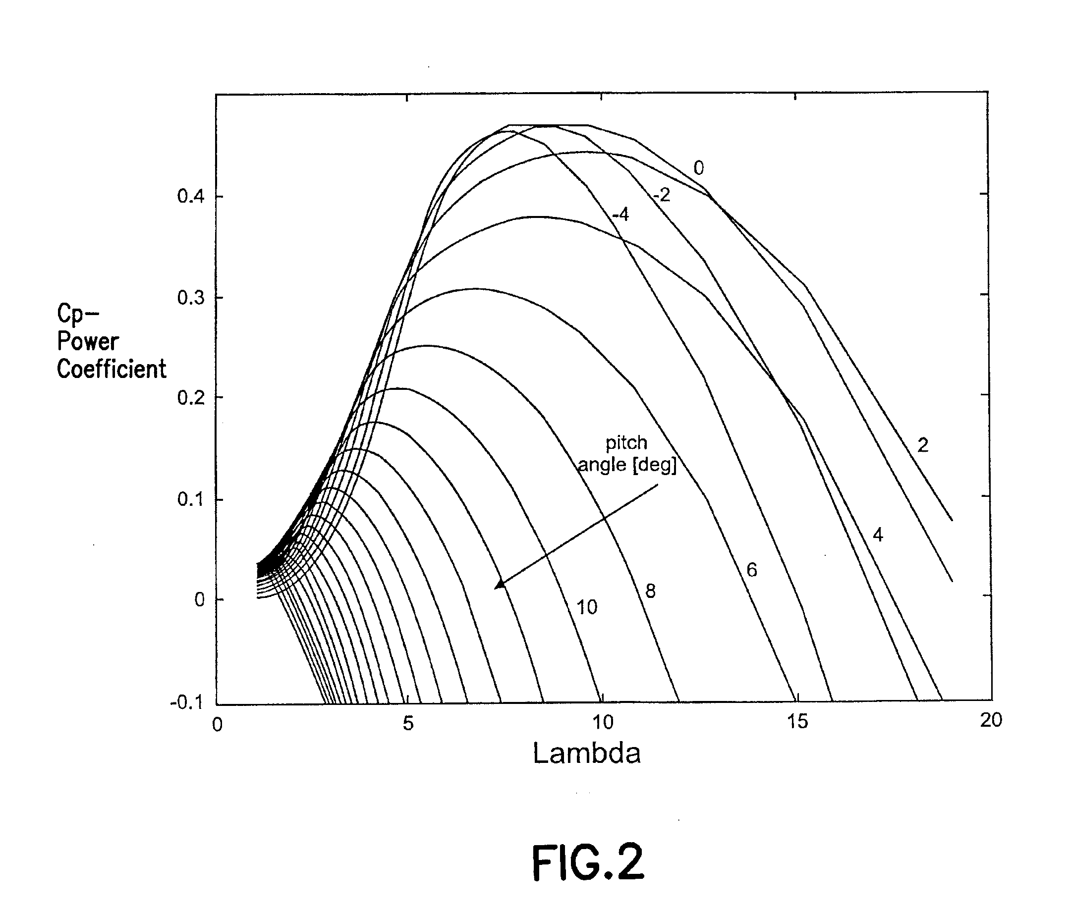
[0050]FIG. 2 illustrates the cp curves which have been previously described and illustrate curves as a function of blade pitch angles and blade tip to wind speed ratio (lambda).

[0051]In general, the power captured by a wind turbine rotor blade system is derived from:

Pel=ηρ2πR2cpv3,[Eq.1]

where η is an efficiency factor, dependent upon the efficiency of the generator, gearbox, etc. and ρ is air density, which is about 1.225 kg / m3 at sea level; R is rotor radius in meters, cp is the fraction of power extracted from the wind, and v is the wind velocity in meters / second.

[0052]...


PUM


Abstract

The present invention relates to an improved wind turbine, of the type which employs doubly fed induction generators (DFIG), and a wind park including the same, which permits the use of lighter weight turbines, with the ability to have greater energy capture, more precise control of asymmetrical phases and enhanced maintenance and support of the grid during fault conditions.

Description

BACKGROUND OF THE INVENTION[0001]1. Field of the Invention[0002]The present invention relates to an improved wind turbine, of the type which employs doubly fed induction generators (DFIG), and a wind park including the same, which permits the use of lighter weight turbines, with the ability to have greater energy capture, more precise control of asymmetrical phases and enhanced maintenance and support of the grid during fault conditions.[0003]Specifically, the present invention relates to wind turbines configured for operation either singly, in small concentrations, or in wind parks, each turbine being a variable speed turbine using a doubly fed induction generator (DFIG) with grid side inverters, having power provided from both their generator stators and rotors, and preferably with major contributions of reactive power for grid voltage support being provided by park level static reactive power sources. As well, the present invention contemplates the use of blade pitch control, whi...

Claims


Application Information

Patent Timeline
Patent Type & Authority Applications(United States)
IPC IPC(8): F03D9/00
CPCF03D7/0224F03D7/0272F03D7/0276F03D7/044F03D9/005H02P2101/15F05B2270/20H02P9/007H02P9/04H02P9/102Y02E10/723F05B2270/1033F03D9/257Y02E10/72F03D7/02
Inventor JORGENSEN, ALLAN HOLMHELLE, LARSSCHAIER, LEONARD
Owner VESTAS WIND SYST AS
Why Eureka
Try Eureka