Optical power limiting and switching combined device and a method for protecting imaging and non-imaging sensors

Inactive Publication Date: 2009-08-20
KILOLAMBDA TECH
View PDF12 Cites 13 Cited by
  • Summary
  • Abstract
  • Description
  • Claims
  • Application Information

AI Technical Summary

Benefits of technology

[0033]When the power is above the damage threshold, break down occurs. Mixtures of nano particles of conducting material in dielectrics are known to enhance the electric field strength in their vicinity where their shape and dispersion induces field concentration, resulting in lower power needed to create an electrical breakdown, and damage. Such mixtures may be modeled as a plurality of aggregates of nano-particles (see, e.g., M. Quinten, “Local Fields Close to the Surface of Nanoparticles and Aggregates of Nanoparticles,” Appl. Phys. B 73, 245-255 (2001) and the book “Absorption and Scattering of Light

Problems solved by technology

Imaging and detection systems, using large-aperture and low F-number telescopes, are susceptible to detector saturation and/or damage caused by a powerful light source or a high power laser within their fields of view.
The problem exists in many cases, especially in modern optical systems wherein active (e.g., laser), together with passive (e.g., television or night-vision, multi-pixel) sensors are used in the same or adjacent systems, when reflected laser light or an arbitrary ray or reflection from a laser enters the imaging system.
This difficulty calls for a passive device that will limit and/or switch-off the power propagating into the sensor or detector, when the power exceeds a maximal allowed intensity or a damaging threshold.
This device does not absorb in the visible and near infrared regions, and it cannot protect optical systems in these regions of the spectrum.
These devices genera

Method used


Image

  • Optical power limiting and switching combined device and a method for protecting imaging and non-imaging sensors
  • Optical power limiting and switching combined device and a method for protecting imaging and non-imaging sensors
  • Optical power limiting and switching combined device and a method for protecting imaging and non-imaging sensors

Examples


Embodiment Construction

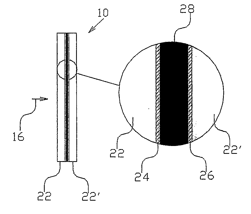
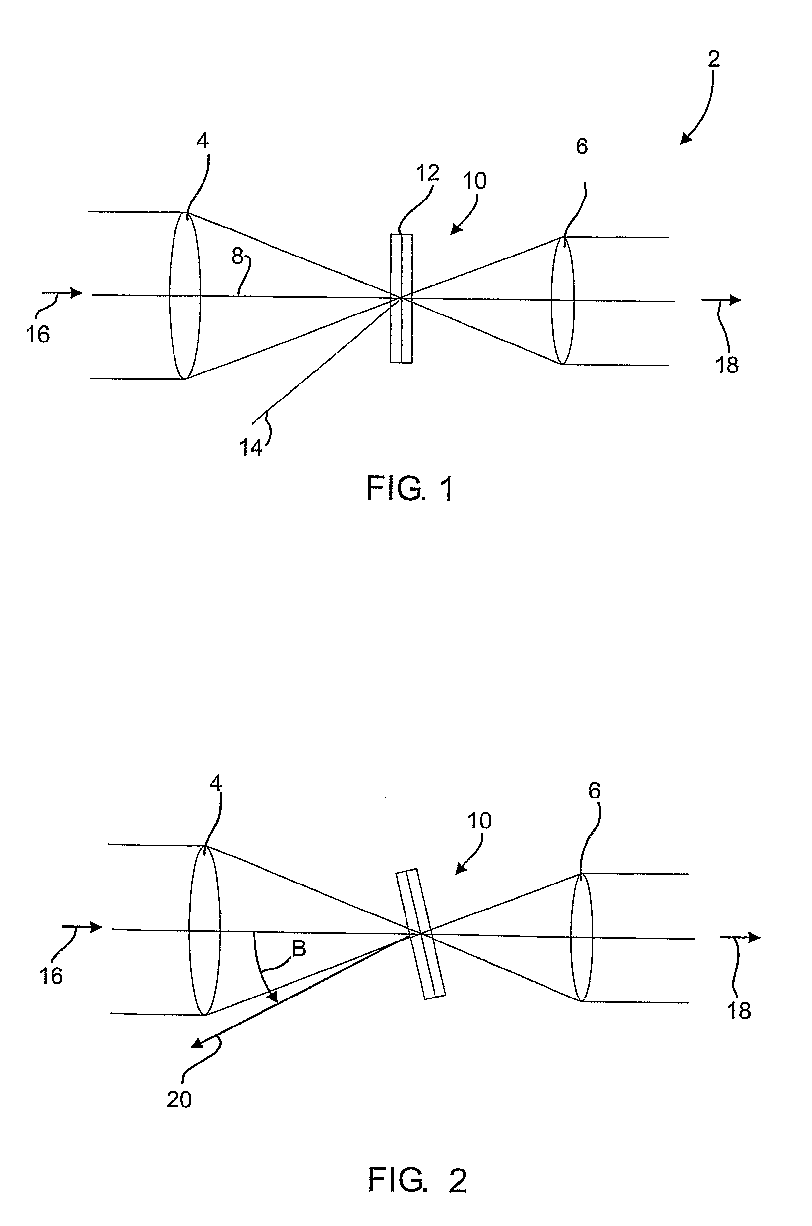
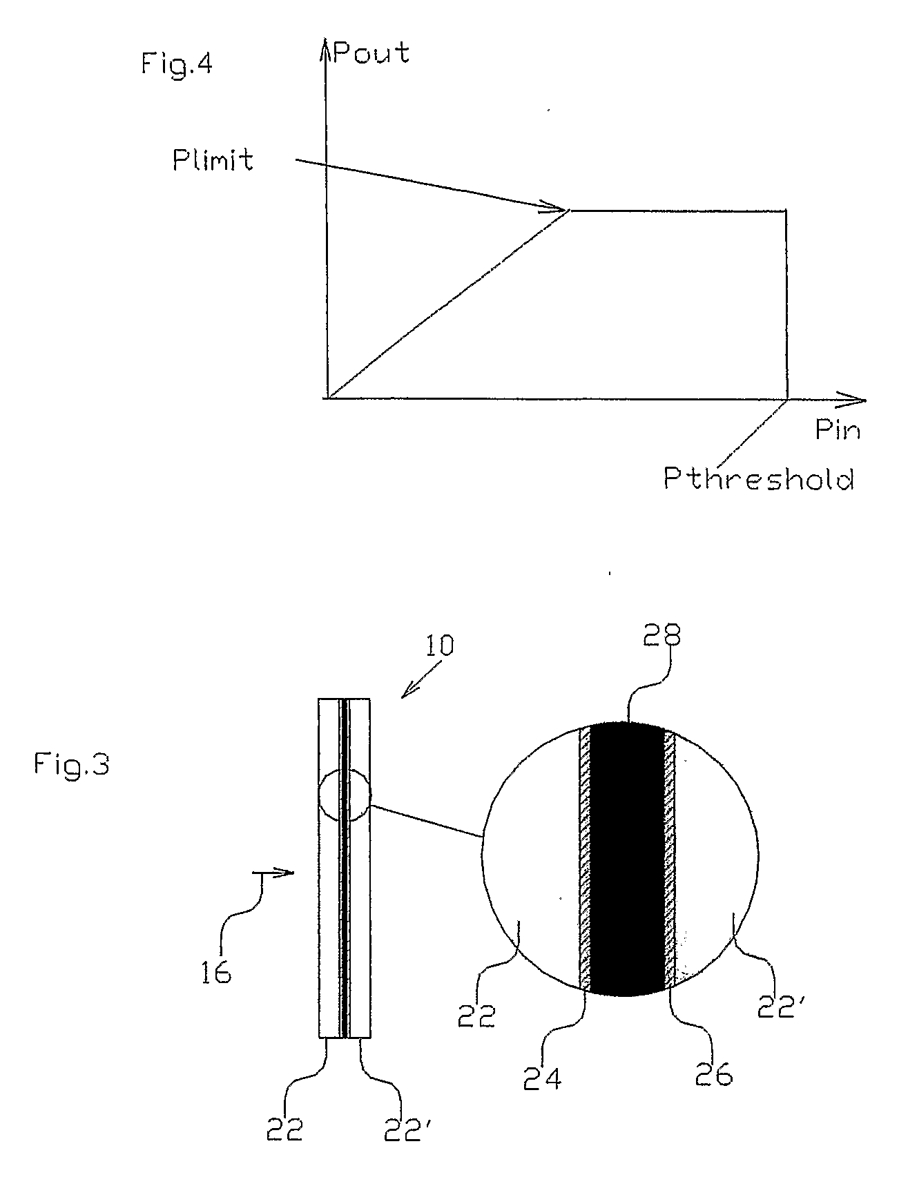
[0045]Referring now to FIG. 1, there is shown a schematic, cross-sectional view of an optical power-limiting and switching system 2 for imaging and non-imaging sensors, having a two-dimensional insert in its cross-over point. The two-dimensional optical power switching system 2 is shown utilized, e.g., with a telescope having an input lens 4 and an output lens 6, disposed along an optical path 8. An optical limiter and switch 10, responsive to optical power, is located on the optical path 8, in a plane 12 traversing the optical path. Plane 12 includes the focal or cross-over point 14, between an input power beam 16 and an output power beam 18, for causing the limiting or interruption of optical power propagation from the input power beam 16 to the output power beam 18 when the optical power exceeds a predetermined threshold.

[0046]FIG. 2 illustrates a method of reducing back-reflected light by tilting the limiter and switch 10 at an angle β / 2, where β is the angle between the input p...


PUM


Abstract

An optical power limiting and switching device comprises at least one plate made of transparent dielectric material, and a thin limiting solid mixture coated on one side of the plate. Upon being exposed to an optical power beam having a power level exceeding a predetermined limit power, the layer of solid mixture limits the power transmission by scattering out part of the impinging energy. When the power increases to the damage threshold, the solid mixture forms a plasma or catastrophic breakdown, damaging the solid mixture material and thereby rendering the portion of the plate surface under the impinging beam opaque to light.

Description

FIELD OF THE INVENTION[0001]The present invention relates to optical power limiting and switching combined device and methods for protecting imaging and non-imaging sensors or other optical components. More particularly, the present invention concerns devices and methods for interrupting and / or limiting optical transmission in response to the transmission of predetermined, excessive optical power or energy, in order to protect imaging and non-imaging sensors, detectors or other optical components.BACKGROUND OF THE INVENTION[0002]Imaging and detection systems, using large-aperture and low F-number telescopes, are susceptible to detector saturation and / or damage caused by a powerful light source or a high power laser within their fields of view. The problem exists in many cases, especially in modern optical systems wherein active (e.g., laser), together with passive (e.g., television or night-vision, multi-pixel) sensors are used in the same or adjacent systems, when reflected laser l...

Claims


Application Information

Patent Timeline
IPC IPC(8): G02F1/01
CPCG02F1/3523H01S3/005G02F1/355G02F1/3525
Inventor ORON, RAMDONVAL, ARIELANEVO, DORONORON, MOSHE
Owner KILOLAMBDA TECH
Why Eureka
Try Eureka