Ducted Air Temperature Sensor

Active Publication Date: 2009-08-20
LENOVO GLOBAL TECH INT LTD
View PDF7 Cites 10 Cited by
  • Summary
  • Abstract
  • Description
  • Claims
  • Application Information

AI Technical Summary

Benefits of technology

[0008]One embodiment of the invention provides a computer system, comprising a chassis securing a circuit board, a fan system mounted in the chassis, wherein the fan system draws air through the chassis and establishes an airflow direction, and a heat-generating component mounted on the circuit board and exposed to the air flow. A hot air duct passively directs air heated by the heat-generating component from a single hot air duct inlet in direct downstream alignment with the heat-generating component to a single hot air duct outlet downstream of the single hot air duct inlet, wherein the hot air duct has a length to width aspect ratio of g

Problems solved by technology

Since excessive heat can lead to component failure, significant efforts are made to design and operate computer systems to prevent components from reaching high temperatures.
However, the fans are

Method used


Image

  • Ducted Air Temperature Sensor
  • Ducted Air Temperature Sensor
  • Ducted Air Temperature Sensor

Examples


example

Comparison of Thermal Sensor Measurements

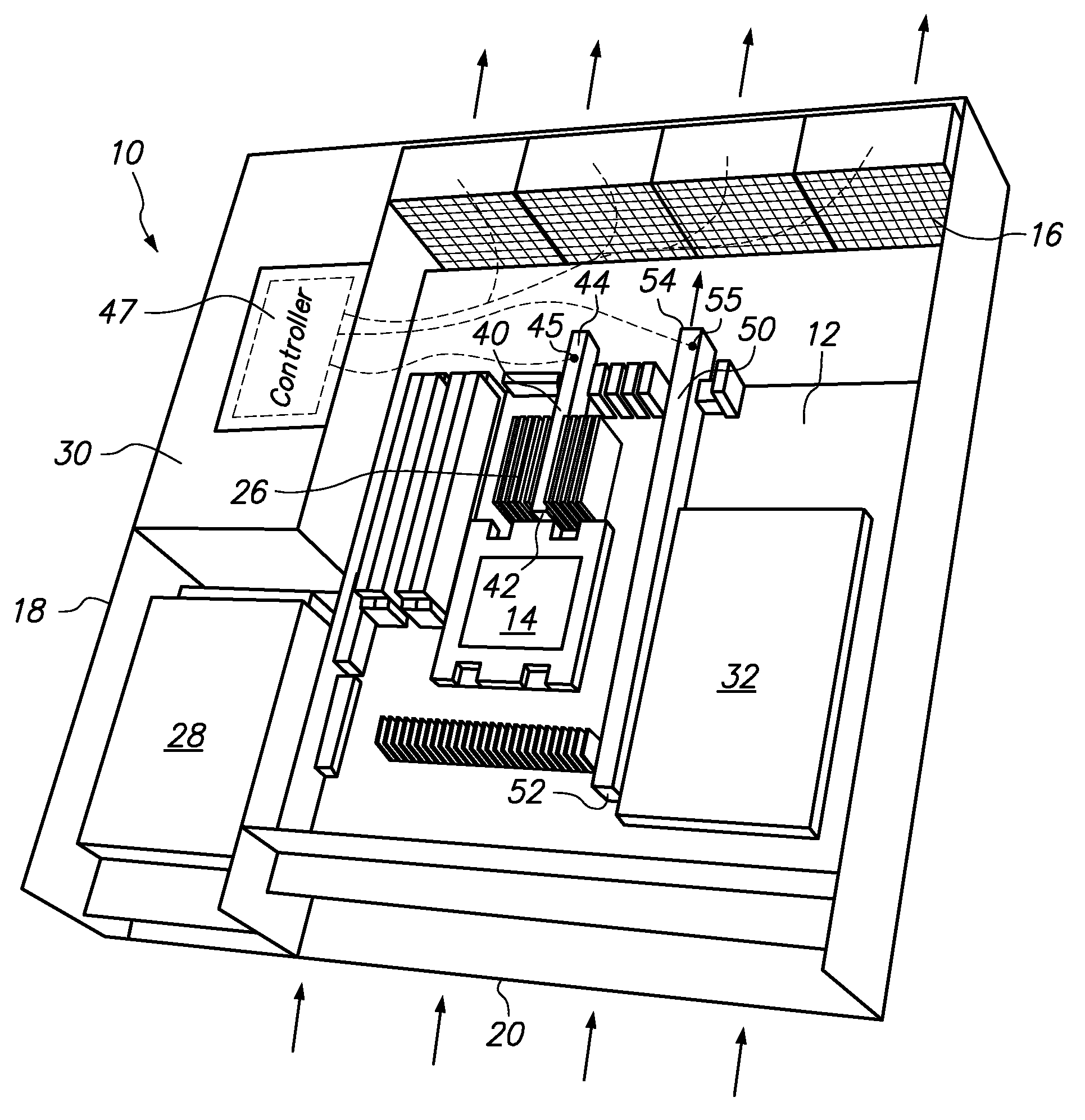
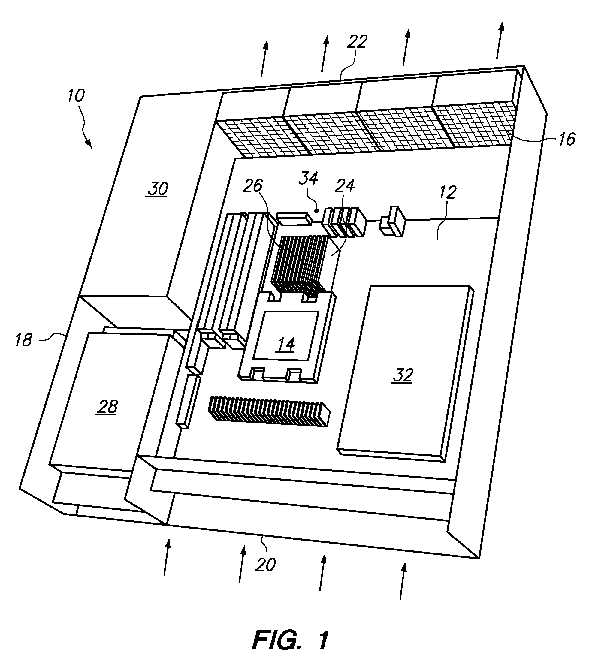
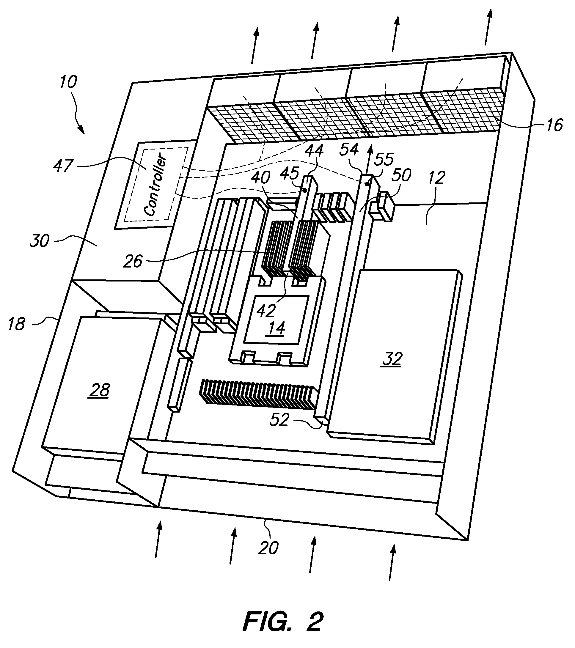
[0031]Two circuit boards were prepared with identical components, layouts and dimensions, then placed into a common chassis having a fan pack that caused an equal amount of air from the same ambient air source to flow across the circuit boards. The first circuit board was laid out as shown in FIG. 1 and the second circuit board was laid out as shown in FIG. 2. The two circuit boards were mounted in separate modules in the common chassis according to FIG. 2, with the second circuit board positioned in the top bay. The two circuit boards were then operated with identical processor loads. For each of the two circuit boards, the temperature of the processor 14 and the temperature at a point directly downstream of the processor 14 at the edge of the circuit board 12 (point 34 in FIG. 1 and point 44 in FIG. 2) was measured. The steady state temperature differential between the processor 14 and point 34 in FIG. 1 was 14 degrees Celsius with wide flu...


PUM


Abstract

A temperature isolation duct in a computer system comprising a chassis securing a circuit board and a fan system, wherein the fan system draws air through the chassis in an airflow direction, and a heat-generating component is mounted on the circuit board and exposed to the air flow. The hot air duct passively directs air heated by the heat-generating component from a single hot air duct inlet in direct downstream alignment with the heat-generating component to a single hot air duct outlet, wherein the hot air duct has a length to width aspect ratio of greater than four. A first thermal sensor is secured within, or direct alignment with, the hot air duct near the duct outlet for sensing the temperature of air flowing through the hot air duct and generating a first temperature signal. A controller is in electronic communication with the first thermal sensor for receiving the temperature signal and in electronic communication with the fan system for sending a fan speed control signal. Optionally, the hot air duct may extend through, over or around a second component on the circuit board to avoid thermal effects of the second component.

Description

BACKGROUND OF THE INVENTION[0001]1. Field of the Invention[0002]The present invention relates to a method and apparatus for sensing the temperature of a heat-generating component of a computer system.[0003]2. Description of the Related Art[0004]Computer systems include many electronic components generate waste heat as a by product of their normal functions. Since excessive heat can lead to component failure, significant efforts are made to design and operate computer systems to prevent components from reaching high temperatures. The most common approach to this problem is the use of forced air convection through computer chassis. For individual computers, sufficient cooling may be achieved using a single fan to circulate room temperature air through the enclosure. However, data centers generally require computer room air conditioning (CRAC) systems and fans that operate within individual chassis or racks.[0005]Fans are necessary to make sure that air is circulated through each unit ...

Claims


Application Information

Patent Timeline
IPC IPC(8): H05K7/20
CPCH05K7/20836H05K7/20727
Inventor GLOVER, TROY WILLIAMSJUNE, MICHAEL SEANKAMATH, VINODSCOTT, III, WHITCOMB RANDOLPH
Owner LENOVO GLOBAL TECH INT LTD
Why Eureka
Try Eureka