Lens, light source unit, backlight apparatus, and display apparatus

a backlight apparatus and light source technology, applied in lighting and heating apparatus, fixed installations, instruments, etc., can solve the problems of color variability, difficulty in disposing led elements independently, and mixing red light, green light, and blue light in a limited space, so as to suppress luminance variability or color variability, the effect of reducing the thickness of the display panel

Inactive Publication Date: 2009-08-20
SATURN LICENSING LLC
View PDF18 Cites 99 Cited by
  • Summary
  • Abstract
  • Description
  • Claims
  • Application Information

AI Technical Summary

Benefits of technology

[0011]In the cylindrical lens disclosed in Patent Document 1 above, light from the point light sources is diffused by the concave lens function (52). However, the cylindrical lens needs to be devised further for realizing a reduction in thickness of the display panel and suppressing luminance variability or color variability.

Problems solved by technology

When using the power-type LEDs, it is difficult to dispose the LED elements independent for each of R, G, and B close to each other due to the problem of the number, size, and heat of the LEDs.
In other words, an increase in distances among the LED elements results in a disadvantage in mixing red light, green light, and blue light in a limited space.
Also in this case, although not many problems are caused when a sufficient optical distance (thickness) can be secured, because it is currently difficult to bring the LED elements close to each other due to the move towards reductions in thickness, color variability is caused.
However, this case also has a limit in terms of color variability.
However, by merely using the LED elements as they are even when the distances are shortened, generation of color variability right above the LEDs cannot be avoided in a backlight assuming thickness reduction.
Moreover, a large variation in RGB light distribution characteristics of the respective LED elements facilitates color variability, which is a large problem.

Method used


Image

  • Lens, light source unit, backlight apparatus, and display apparatus
  • Lens, light source unit, backlight apparatus, and display apparatus
  • Lens, light source unit, backlight apparatus, and display apparatus

Examples


Embodiment Construction

[0069]Hereinafter, embodiments of the present invention will be described with reference to the drawings.

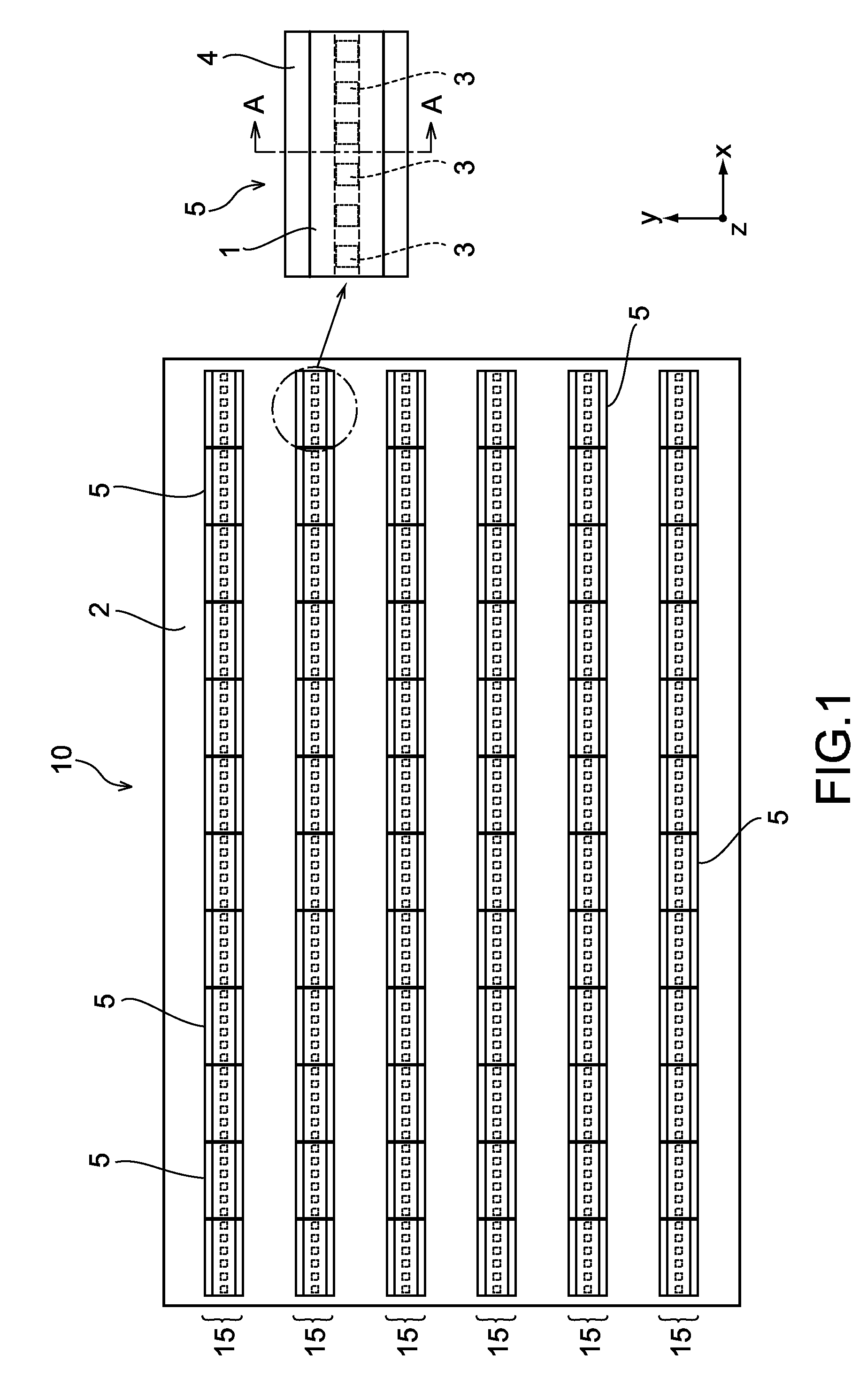
[0070]FIG. 1 is a diagram showing a backlight apparatus according to an embodiment of the present invention.

[0071]A backlight apparatus 10 includes a plurality of light source units 5 and a supporting member 2 for supporting the light source units 5. The backlight apparatus 10 is applied to a display apparatus that uses a light transmission control panel (not shown). A typical example of the light transmission control panel is a liquid crystal panel, though any panel may be used as long as it can variably control light transmission of a backlight for each pixel.

[0072]When the backlight apparatus 10 is applied to the display apparatus, an optical sheet (not shown) such as a diffusing sheet and a prism sheet is interposed between the backlight apparatus 10 and the light transmission control panel in some cases.

[0073]The supporting member 2 may be of a substrate type or a frame type...


PUM

PropertyMeasurementUnit
lengthaaaaaaaaaa
Sizesaaaaaaaaaa
Sizesaaaaaaaaaa

Abstract

A lens diffusing light emitted from a light source includes a concave light-incident surface, a light guide portion, and a light-emitting surface. The light-incident surface includes a plane portion opposed to the light source and an optical function portion that is formed on the plane portion and one of scatters and diffuses the light. The light emitted from the light source enters the light-incident surface. The light that has entered the light-incident surface passes through the light guide portion. The light-emitting surface emits the light passed through the light guide portion.

Description

CROSS REFERENCES TO RELATED APPLICATIONS[0001]The present invention contains subject matter related to Japanese Patent Application JP 2008-034627 filed in the Japanese Patent Office on Feb. 15, 2008, the entire contents of which being incorporated herein by reference.BACKGROUND OF THE INVENTION[0002]1. Field of the Invention[0003]The present invention relates to a backlight apparatus used in, for example, a display apparatus, a lens used in the backlight apparatus, a light source unit, and a display apparatus equipped with the backlight apparatus.[0004]2. Description of the Related Art[0005]Currently, use of LEDs (Light Emitting Diodes) independent for each of R (red), G (green), and B (blue) has contributed to achieving an NTSC (National Television System Committee) ratio of 100% or more in backlights of a high color range used for liquid crystal panels. Therefore, commodification of the backlights in PCs (Personal Computers), amusement equipment, in-car equipment, and TVs is expec...

Claims


Application Information

Patent Timeline
Patent Type & Authority Applications(United States)
IPC IPC(8): F21V13/02G02B5/02F21S2/00F21Y105/00G02B3/00G02B3/06G02F1/13357H01L33/48H01L33/58H05B33/02H05B33/14
CPCG02B5/021G02B5/0268G02B5/0278G02B19/0066G02F1/133606G02B19/0014F21K9/52F21V5/04G02B19/0028F21V5/043
Inventor ARAI, TAKEOMORIMOTO, JUNJI
Owner SATURN LICENSING LLC
Why Eureka
Try Eureka