
Lighting apparatus

a technology of lighting apparatus and light source, which is applied in the direction of lighting and heating apparatus, process and machine control, instruments, etc., can solve the problems of large amount of generated heat, high-power diodes with per-unit power consumption of 1 w or more, and insufficient life of fluorescent lamps of around 6,000 hours, etc., to reduce generated heat and power consumption

Inactive Publication Date: 2009-08-20
MOMO ALLIANCE
View PDF1 Cites 9 Cited by
  • Summary
  • Abstract
  • Description
  • Claims
  • Application Information

AI Technical Summary

Benefits of technology

The present invention is a lighting apparatus that uses solid state light emitting devices, such as light emitting diodes, as a light source. The invention aims to reduce heat and power consumption of the light emitting devices to prevent deterioration of their performance and to prevent environmental pollution. The invention achieves this by efficiently discharging heat generated by the light emitting devices and reducing the total amount of heat generated by the entire lighting apparatus. The lighting apparatus includes a voltage supply unit and a plurality of solid state light emitting devices which are series-connected, and the voltage supplied is set to a level such that the current flowing through each device is equal to or less than 1 / N of the maximum rated current, where N is a number equal to or greater than 2. The invention also includes one or more solid state light emitting device rows in which as many solid state light emitting devices as the plurality of solid state light emitting devices are parallel-connected, to achieve the required light emission quantity while reducing heat and power consumption of each device.

Problems solved by technology

In addition, although fluorescent lamps last longer than incandescent bulbs, the life of fluorescent lamps of around 6,000 hours is not necessarily sufficient.
However, light emitting diodes used in lighting applications are high-power diodes with per-unit power consumption of 1 W or more.
With high-power light emitting diodes, since the power consumption is large, the amount of generated heat is also large.
Accumulation of this heat in the vicinity of light emitting diodes leads to declines in light intensity, deterioration of life characteristics and the like of the light emitting diodes.
In the worst case, non-lighting of light emitting diodes may occur.

Method used


Image

  • Lighting apparatus
  • Lighting apparatus
  • Lighting apparatus

Examples


first embodiment

[0123]First, a configuration of the lighting apparatus according to the first embodiment of the present invention is described.

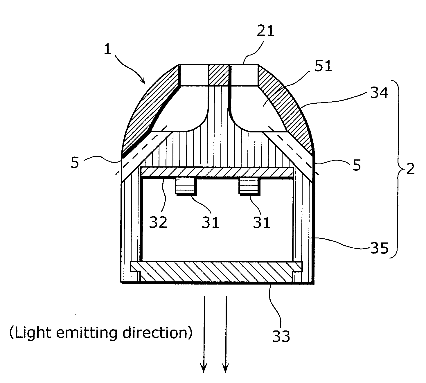
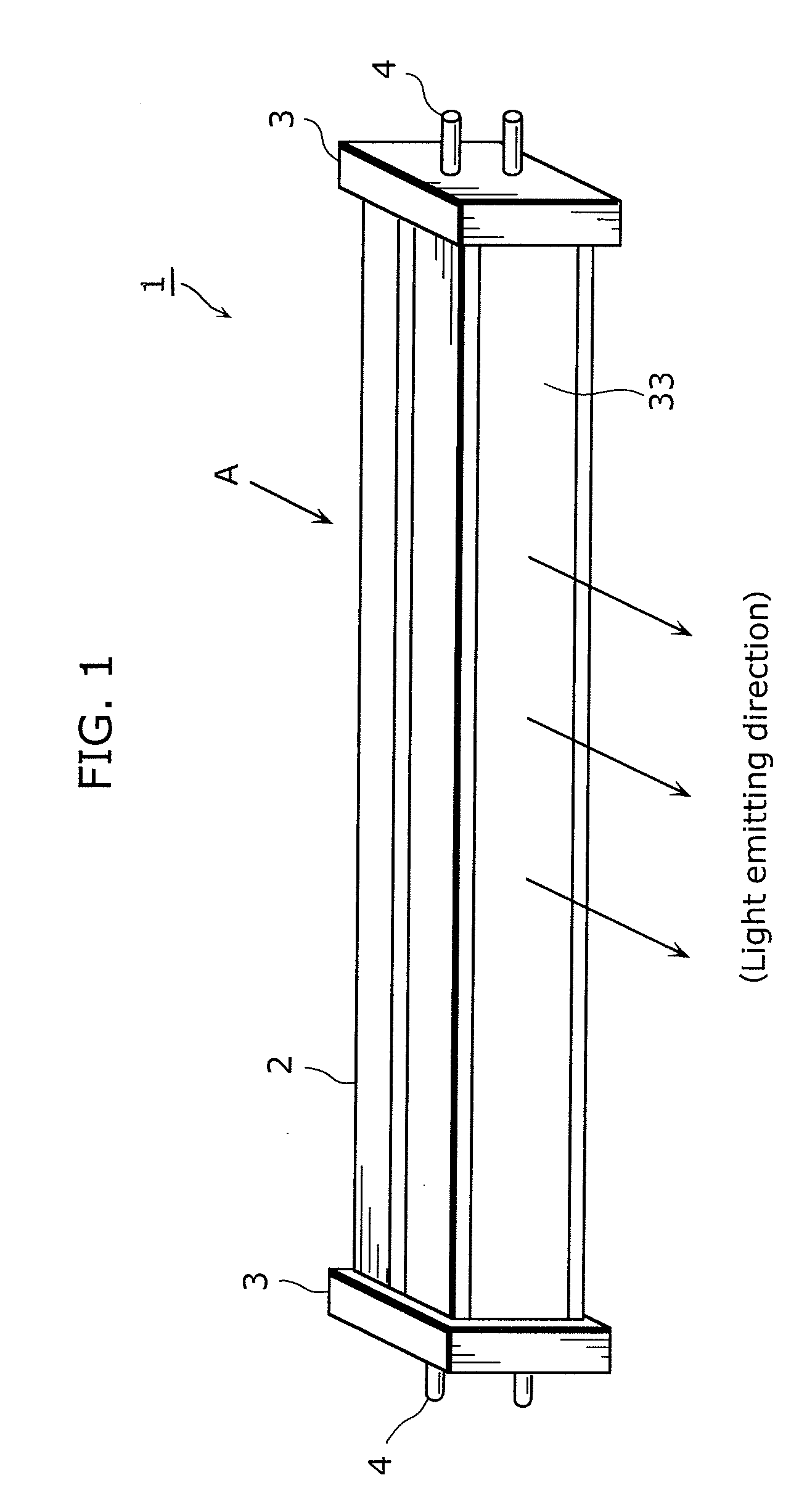
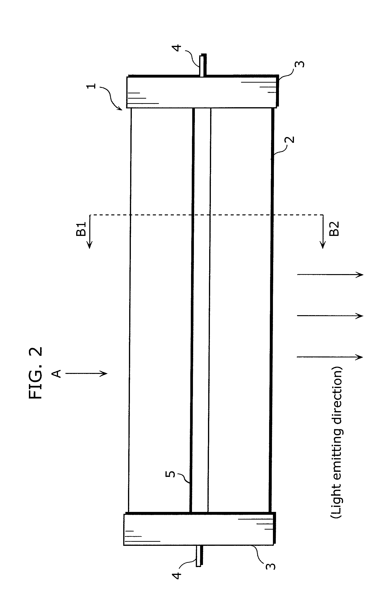
[0124]FIG. 1 is a perspective view showing the exterior of a lighting apparatus 1 according to a first embodiment of the present invention. FIG. 2 is a plan view taken from a lateral surface of the lighting apparatus 1 according to the first embodiment of the present invention. FIG. 3 is a plan view taken from an upper surface (the direction A shown in FIG. 1) of the lighting apparatus 1 according to the first embodiment of the present invention. FIG. 4 is a cross sectional diagram showing a structure of the lighting apparatus 1 taken along the B1-B2 plane shown in FIG. 2. FIG. 5 is a diagram showing a state in which the lighting apparatus 1 is mounted on a bracket 41 of a double-capped fluorescent lamp. FIG. 6 is a cross sectional diagram showing structures of the lighting apparatus 1 and the bracket 41 taken along the C1-C2 plane shown in FIG. 5.

[0125]As s...

second embodiment

[0229]In a lighting apparatus according to a second embodiment of the present invention, due to two diode bridge circuits provided in the lighting apparatus, a pair of terminals to which alternating current power is not provided from an external source is not affected by externally-provided alternating current power. As a result, the lighting apparatus according to the second embodiment of the present invention can be used in replacement of a conventional fluorescent lamp with fluorescent lamp brackets of various types.

[0230]First, a configuration of the lighting apparatus according to the second embodiment of the present invention will be described.

[0231]FIG. 15 is a perspective view showing the exterior of a lighting apparatus 101 according to the second embodiment of the present invention. FIG. 16 is a plan view taken from a lateral surface (the direction A shown in FIG. 15) of the lighting apparatus 101 according to the second embodiment of the present invention. FIG. 17 is a pl...

third embodiment

[0309]A lighting apparatus according to a third embodiment of the present invention is capable of efficiently discharging heat generated inside the lighting apparatus into the air by having a hollow structure inside the casing and utilizing peripheral air convection. As a result, a lighting apparatus according to the present invention achieves an improvement in heat discharge effectiveness.

[0310]As described above, in the lighting apparatus 101 according to the second embodiment of the present invention, high power light emitting diodes are used as the solid state light emitting devices 131 in order to obtain sufficient illuminance. With light emitting diodes, a major portion (approximately 80%) of inputted energy turns into heat as loss. High power light emitting diodes have high power consumption, and accordingly, a significant amount of energy is discharged as heat. Accumulation of this heat in the vicinity of light emitting diodes leads to a decline in luminous intensity, a dete...


PUM


Abstract

A lighting apparatus according to the present invention includes: a voltage supply unit which supplies voltage; and a plurality of solid state light emitting devices which emit light using the voltage supplied by the voltage supply unit. The plurality of solid state light emitting devices are series-connected, the voltage supplied by the voltage supply unit is applied to the plurality of solid state light emitting devices which are series-connected, and the voltage supplied is set to a voltage such that a current flowing through each of the plurality of solid state light emitting devices is equal to or less than 1 / N of the maximum rated current, where N is a number equal to or greater than 2.

Description

TECHNICAL FIELD[0001]The present invention relates to a lighting apparatus, and particularly, to a lighting apparatus that uses solid state light emitting devices such as light emitting diodes as a light source.BACKGROUND ART[0002]Conventionally, fluorescent lamps are used for lighting apparatuses. Fluorescent lamps are superior to incandescent bulbs in efficiency, product life and the like. Accordingly, fluorescent lamps are in widespread use.[0003]However, albeit in a small quantity, mercury is used in fluorescent lamps. Mercury is a toxic substance which, when ingested by an ordinary person, causes nerve damage as typified by Minamata disease. Accordingly, in step with the increase in environmental consciousness in recent years, the RoHS (Restriction of the use of certain Hazardous Substance in electrical and electronic equipment) Directive has taken effect in Europe, thereby initiating the restriction of use of mercury.[0004]In addition, although fluorescent lamps last longer th...

Claims


Application Information

Patent Timeline
Patent Type & Authority Applications(United States)
IPC IPC(8): F21V3/00H01J7/24H05B37/02F21K99/00F21Y101/00
CPCF21V15/01F21V29/004F21Y2101/02F21Y2103/003F21Y2105/001H05B33/0803F21V29/83Y02B20/383F21K9/17F21V29/20F21V29/74F21V29/763H05B33/0809F21Y2105/10F21K9/27F21Y2103/10F21Y2115/10Y02B20/30H05B45/3578
Inventor NAKAYAMA, SADATSUGUNAGAMUNE, SIGERUMAKABE, ATSUSHIGEIKEDA, KOJIDOI, KENTAKATAOKA, NAOKIITO, HIROSHIKAWAI, YUKITOSHI
Owner MOMO ALLIANCE
Learn More