Medical Device Placement and Monitoring System Utilizing Radio Frequency Identification

a technology of radio frequency identification and placement of medical devices, applied in the field of medical devices, can solve the problems of increasing the difficulty of health care providers in ensuring proper placement of either nasogastric or endotracheal tubes, numerous health problems for patients, and aspiration by proxy, and achieve the effect of improving staff efficiency

Inactive Publication Date: 2009-08-20
NG ET OPTIMIZER
View PDF31 Cites 62 Cited by
  • Summary
  • Abstract
  • Description
  • Claims
  • Application Information

AI Technical Summary

Benefits of technology

[0029]A further object of the present invention is to provide a nasogastric or endotracheal tube pl

Problems solved by technology

Although nasogastric insertions or endotracheal intubations are widely used, standard techniques in hospitals, long term care facilities, hospices, and in-home health care delivery, it continues to be challenging for health care providers to assure proper placement of either a nasogastric or endotracheal tube.
The inadvertent misplacement of nasogastric tubes by health care providers has caused numerous health problems for patients.
Aspiration by proxy is a serious consequence of inadvertent misplacement of a nasogastric tube.
This occurs when food or medicine is introduced by a nasogastric tube directly into the lungs, which can cause aspirated pneumonia with its associated increased incidence of morbidity and mortality.
Improper nasogastric tube placement has led to laryngeal injuries due to placement in the trachea and distal airways, when the organ of interest was the stomach.
Other related issues include hypersalivation, depressed cough reflex, and pharyngeal abnormalities.
Complications from improper tube positioning often result in extended hospital stays, or in some instances, may result in death.
While radiographic confirmation does assure correct placement of a nasogastric tube, the patient is exposed to radiation, and the cost of radiographic confirmation is costly and radiographic confirmation is difficult or

Method used


Image

  • Medical Device Placement and Monitoring System Utilizing Radio Frequency Identification
  • Medical Device Placement and Monitoring System Utilizing Radio Frequency Identification
  • Medical Device Placement and Monitoring System Utilizing Radio Frequency Identification

Examples


second embodiment

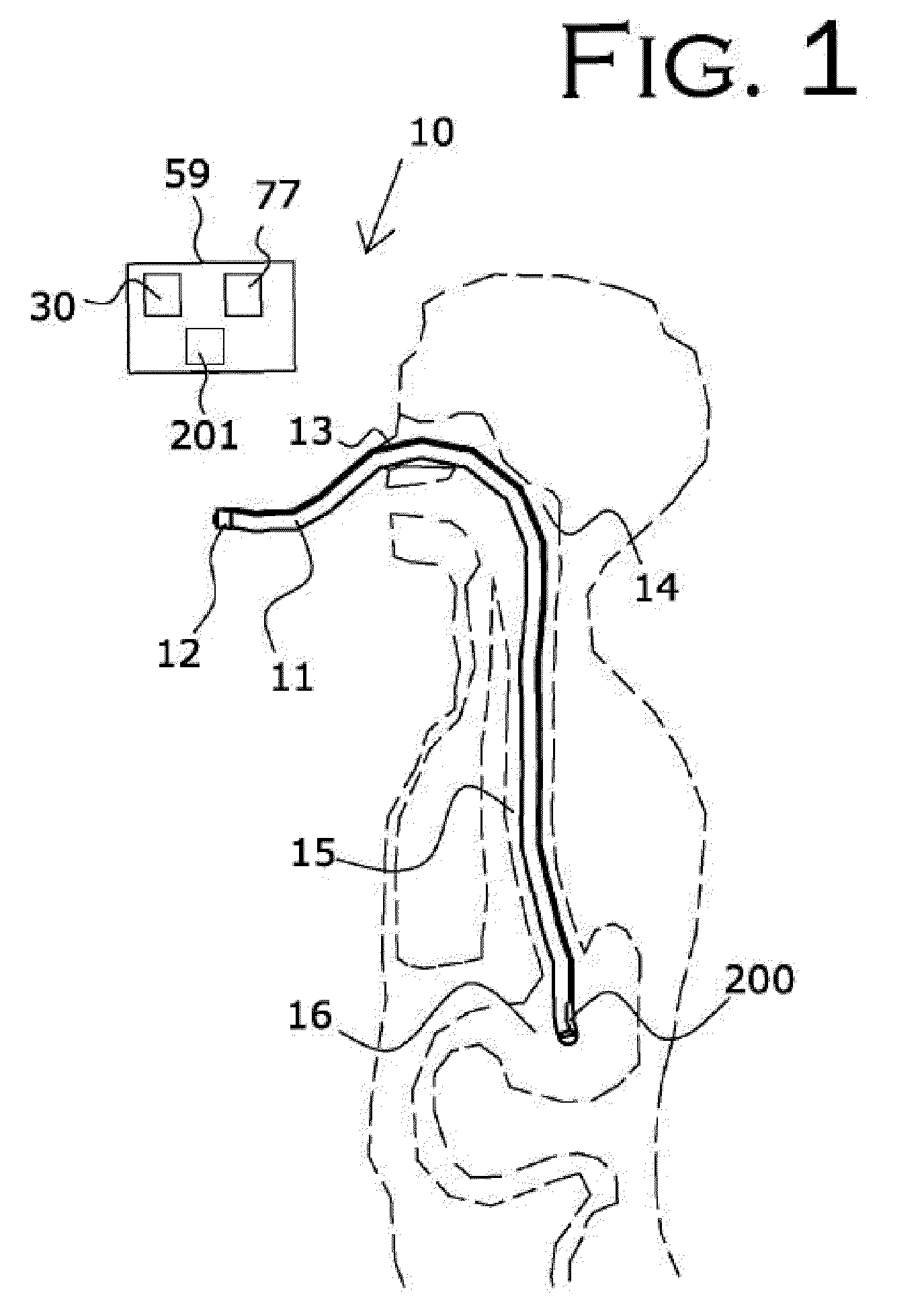
[0093]In a second embodiment, shown in FIG. 7 and FIG. 8, an audio monitoring circuit is illustrated, with the flowchart of FIG. 8 illustrating an overview of the operation of the audio monitoring circuit. The feedback initiator within the RFID tag 200 at the distal end of flexible tube 11 is an acoustic port 20b or opening using tube 11 as a means for sound to travel to the microphone 32 on the proximal end of tube 11, FIG. 7.

[0094]Feedback initiator 20 in the second embodiment preferably comprises a microphone 32 to receive the sounds from the distal end of flexible tube 11 configured with the appropriate amplifiers to amplify the received sounds and the appropriate circuitry to transmit the sounds via an RF transmitter to the speaker 38 which is configured with the appropriate circuitry to generate an audible sound that can be heard by the clinicians. The speaker 38 serves as a notifying device that provides the clinician with information concerning the distal end of flexible tub...

third embodiment

[0096]Illustrated in FIG. 9 and FIG. 10 is a third embodiment, an air pressure circuit to monitor air flow so that the attending clinician can ascertain whether the nasogastric tube is located in the airway or not, either during intubation or after intubation. The feedback initiator connected to the proximal end of flexible tube 11 is an air pressure sensor 20d. The air pressure sensor 20d is configured to measure the pressure or airflow of the air at the distal end of flexible tube 11. The detected air pressure data is transmitted to the feedback receiver, air pressure monitor 30d via an RF signal communicated from an RF transmitter at the proximal end of tube 11 to the feedback receiver, air pressure monitor 30d. Air pressure monitor 30d is configured with the appropriate electronics to receive the information from the air pressure sensor 20d, to analyze the information to determine if the information is appropriate for the organ of interest, and to send a signal to activate the n...

first embodiment

[0101]Air pressure sensor 20d then takes readings and transmits the resultant data back to the feedback receiver via an RF signal as described in association with the The feedback receiver, an air pressure monitor 30d, is configured with the appropriate circuitry and electronics to receive the RF signal transmitted from air pressure sensor 20d and to analyze it. If the air pressure reading is appropriate 41 for the organ of interest, the air pressure sensor 20d merely continues to monitor the air pressure.

[0102]If the air pressure reading is inappropriate 42 for the organ of interest, the feedback receiver 30d causes the notifying devices to be activated. Warning buzzer 18 emits an audible alarm and / or the warning indicator light 19 is lighted, thus producing a visual and auditory signal and notification to the clinician of the problem. These may automatically reset after a given amount of time, or alternatively, as shown, they may be manually reset when the clinician depresses res...


PUM


Abstract

A medical device placement and monitoring system is provided that includes numerous circuits that can be used alone or in combination. The circuits include a feedback initiator, a feedback receiver, and a clinician notifying device. By various means in the provided circuits, the feedback initiator provides information about the location of a radio frequency identification tag secured to a medical device inserted within a patient. This information or data is received and analyzed by the feedback receiver that monitors the circuit, which then transmits an output to the clinician notifying device to alert or advise the attending clinician of this information. The data that is output supplies information about the location of the radio frequency identification tag to the clinician, thereby assisting the clinician in placement of a variety of medical devices including nasogastric or endotracheal tubes, as well as in monitoring proper device placement after initial insertion.

Description

CROSS REFERENCE TO RELATED APPLICATIONS[0001]This application is a continuation-in-part of Ser. No. 11 / 799,664, filed with the U.S. Patent and Trademark Office on May 2, 2007, which is herein incorporated by reference in its entirety.STATEMENT REGARDING FEDERALLY SPONSORED RESEARCH OR DEVELOPMENT[0002]Not applicable.INCORPORATION-BY-REFERENCE OF MATERIAL SUBMITTED ON A COMPACT DISK[0003]Not applicable.BACKGROUND OF THE INVENTION[0004]1. Field of the Invention[0005]The present invention relates generally to a medical device that is used to correctly place and monitor either a nasogastric tube during insertion procedures into the stomach or an endotracheal tube for patient airway intubations into the lungs. This medical device serves as a placement and monitoring system configured to assure proper placement—either into the stomach for a nasogastric tube or into the lungs for an endotracheal tube—and monitoring thereafter of either the nasogastric or endotracheal tube. The system is co...

Claims


Application Information

Patent Timeline
IPC IPC(8): A61B5/05G08B5/22
CPCA61B5/0008A61B5/0031A61B5/14539A61B5/083A61B5/06A61B5/062
Inventor ROWE, PHILIP STEPHENSPRAKER, JR., JIMMIE HANSON
Owner NG ET OPTIMIZER
Why Eureka
Try Eureka